Five-axis CNC machines are critical in high-precision industries such as aerospace, wind energy, and nuclear power, where complex geometries and stringent tolerances are standard. The dynamic accuracy of these machines directly impacts product quality and production efficiency. This article presents a practical, cost-effective method for rapid dynamic accuracy testing of five-axis CNC machines, leveraging existing machine compensation functions, precision tools, and macro programs to achieve reliable results. The approach ensures high precision while minimizing time and cost, making it suitable for regular maintenance and pre-production checks in aerospace manufacturing.
Background of Five-Axis Dynamic Accuracy Testing
Five-axis CNC machines are sophisticated systems with multiple motion axes, enabling complex multi-angle machining. Their dynamic accuracy, which reflects the combined precision of all motion components during operation, is a key determinant of machining performance. Unlike static accuracy, which measures individual component precision under no-load conditions, dynamic accuracy captures the machine’s behavior under operational conditions, closely mimicking actual production scenarios.
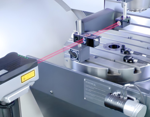
Traditional dynamic accuracy testing relies on infrared laser equipment to measure single-axis motion in real time. This method involves clearing existing compensation values, performing segmented variable-speed tests, and inputting data into the machine’s control system (e.g., TNC) to generate compensation codes for mechanical gap correction. While effective, this approach is time-consuming, costly, and limited in its ability to assess comprehensive motion accuracy under load. These limitations necessitate a faster, more cost-effective method to maximize the productivity of five-axis machines in aerospace manufacturing.
Proposed Rapid Dynamic Accuracy Testing Method
The proposed method leverages the inherent capabilities of five-axis CNC machines, specifically the Real-Time Tool Center Point (RTCP) function, combined with precision tools such as a measurement ball, dial indicator, and macro programs. This approach ensures rapid and accurate dynamic accuracy testing while maintaining low costs. Below is a detailed breakdown of the implementation steps.
Step 1: Static Accuracy Verification
Static accuracy forms the foundation for dynamic accuracy. Before conducting dynamic tests, the machine’s static accuracy must be verified. This typically occurs during annual secondary maintenance, where geometric and positional accuracies are measured and compensated. Key parameters include spindle runout, perpendicularity, linearity, flatness, repeatability, and backlash for the X, Y, Z, A, and C axes. For rapid dynamic testing, a quick re-verification is performed using a dial indicator to measure spindle runout, backlash, and C-axis rotational limits, eliminating the need for laser interferometers.
This step ensures that the machine’s baseline accuracy is intact, reducing variables that could affect dynamic testing results. The verification process typically takes a few hours, depending on the machine’s condition and prior maintenance records.
Step 2: Precision Measurement Ball Preparation
A custom-designed measurement ball with a diameter of 80 mm and a radius of 40 mm is used for dynamic testing. The ball’s specifications are critical to ensure measurement reliability:
- Diameter and roundness tolerance: ≤0.005 mm
- Surface roughness: Ra < 0.8 μm
- Finish: Mirror-like to minimize hardware-induced errors
The measurement ball serves as a reference for tracking the machine’s motion trajectory during dynamic tests, ensuring 高精度 in detecting deviations.
Step 3: Calibration of Five-Axis Head Compensation Values
The fixed rotation compensation values of the five-axis head, determined at the factory, must be recalibrated due to potential changes from prolonged use or maintenance. A standard bar with a known length (150 mm) and radius (25 mm) is used for calibration. The process involves:
- Establishing a coordinate system at the center of the standard bar.
- Positioning a dial indicator to contact the bar’s maximum outer diameter, compressing the indicator by 0.1 mm, and zeroing it.
- Manually moving the X-axis to a safe position, rotating the A-axis to 90 degrees, and zeroing the dial indicator against the spindle face.
- Calculating the compensation value using the formula: Five-axis head compensation = Measured value – Standard tool length (150 mm) – Standard bar radius (25 mm).
During this process, the RTCP function is disabled to ensure accurate measurement of mechanical offsets. This step ensures that the machine’s compensation parameters align with its current mechanical state.
Step 4: RTCP-Based Dynamic Accuracy Testing
The RTCP function, also known as tool center point control, enables precise multi-axis motion by mathematically transforming the programmed control point to the actual tool contact point. By integrating RTCP into the testing process, the method ensures that the machine’s theoretical motion trajectory matches the programmed NC code, allowing accurate tracking of dynamic performance.
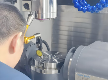
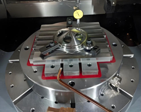
The dynamic testing setup involves:
- Setting the Dynamic Rotation Point: A dial indicator is fixed to contact the measurement ball’s surface (80 mm diameter, 40 mm radius). The rotation point is set as the coordinate system origin by manually locating point B (on the ball’s surface) and offsetting to point A, establishing the test coordinate system.
- Adjusting Tool Length Compensation: The tool compensation value is reduced by the ball’s radius (40 mm) and set as the tool length compensation (D01) for the test program.
- Running the Macro Program: A macro program is executed to perform multi-angle, multi-axis linkage tests. The program commands the machine to move through predefined angles (e.g., A-axis ±90°, C-axis ±90°, and ±45°) at a feed rate of 1000 mm/min, simulating dynamic motion.
The macro program is structured as follows:
| Line | Code | 説明 |
|---|---|---|
| N1-N2 | #1=90, #2=45 | Define rotation angles for A and C axes |
| N3-N4 | TROFOOF, M06 T01 D01 | Disable transformation, select tool and compensation |
| N5-N9 | G0 A0 C0, G90 G54 G01 Z100 F5000, X0 Y0, Z0 | Initialize position and move to starting point |
| N11-N24 | G01 A=#1, A=-#1, A0, C=#1, C=-#1 | Perform A and C axis rotations for testing |
| N26-N34 | C=#2, G01 A=#1, A=-#1, A0, C=-#2 | Test additional C-axis angles |
This program ensures comprehensive testing of the machine’s dynamic accuracy across multiple axes and angles, capturing real-time performance data.
Step 5: Validation of Test Results
To confirm the accuracy of the dynamic testing method, results are compared with three-coordinate measurements of test-cut parts. The error correlation between dynamic test data and actual part measurements ranges from 96% to 98%, validating the method’s reliability. This high correlation demonstrates that the proposed approach effectively captures the machine’s dynamic performance, making it suitable for routine maintenance and pre-production checks.
Implementation Benefits
The rapid dynamic accuracy testing method offers several practical benefits:
- コスト効率: By using existing machine functions (RTCP) and affordable tools (measurement ball, dial indicator), the method eliminates the need for expensive laser equipment.
- Time Savings: The process can be completed in a few hours, compared to days for traditional laser-based methods, enabling frequent testing during weekly or monthly maintenance.
- Accuracy: The method achieves a 96–98% correlation with actual machining outcomes, ensuring reliable results for aerospace applications.
- Practicality: The use of macro programs and standard tools makes the method accessible to technicians without specialized training in laser-based systems.
This approach has been integrated into weekly and monthly maintenance schedules in aerospace manufacturing facilities, ensuring consistent machine performance and high-quality output.
Technical Considerations
While the method is highly effective, certain considerations ensure optimal results:
- Tool Precision: The measurement ball and standard bar must meet stringent tolerances to avoid introducing errors.
- Operator Skill: Technicians must be trained to set up the coordinate system and execute the macro program accurately.
- Machine Condition: Static accuracy must be verified before dynamic testing to ensure reliable results.
- Environmental Factors: Temperature and vibration control in the testing environment are critical to avoid external influences on measurements.
Addressing these considerations ensures the method’s repeatability and reliability across different machines and facilities.
結論
The rapid dynamic accuracy testing method for five-axis CNC machines provides a practical, cost-effective solution for aerospace manufacturing. By leveraging the RTCP function, precision tools, and macro programs, the method achieves high accuracy with minimal time and cost. Its successful implementation in regular maintenance and pre-production checks demonstrates its value in ensuring product quality and production efficiency. The approach’s simplicity and reliability make it a valuable tool for manufacturers seeking to optimize five-axis CNC machine performance.