
In precision mechanical manufacturing, machining small-diameter rods with stringent coaxiality and dimensional accuracy requirements poses significant challenges, particularly when conventional cylindrical grinders are inadequate. This article outlines a method for machining coaxial precision rods using a small precision surface grinder, such as the JL-618, equipped with a universal precision dividing head. The process leverages existing equipment and auxiliary tools to achieve high-precision results, offering a practical solution for components like measurement and positioning rods used in specialized gauges.
Overview of Coaxial Precision Rod Machining
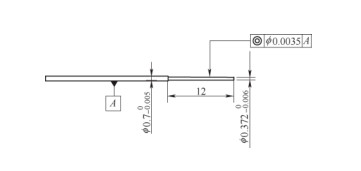
Coaxial precision rods, often integral to specialized gauges, require high dimensional accuracy, tight coaxiality tolerances, and excellent surface finish. These rods, typically with diameters as small as 0.372 mm, are critical to the functionality of the gauges they serve. Traditional cylindrical grinding struggles with such small diameters due to difficulties in achieving stable and precise positioning, particularly when using conical tip fixtures. This method utilizes a surface grinder and a universal dividing head to address these limitations, ensuring stable clamping, precise alignment, and controlled material removal.
Difficulties in Conventional Cylindrical Grinding
Conventional cylindrical grinding relies on two primary positioning methods for coaxial rods:
- Large-Diameter Rods: During rough turning, center holes are machined at both ends. After heat treatment, these holes are refined to serve as positioning references for cylindrical grinding.
- Small-Diameter Rods: A center hole is machined at the thicker end, while the thinner end is turned to a sharp point. After heat treatment, the center hole is refined, and the sharp end is ground to form a 60° conical tip, which acts as a positioning reference.
For small-diameter rods, the conical tip's surface area diminishes as the diameter decreases, complicating precise positioning. The internal conical fixture (concave tip) used to secure the 60° conical tip becomes critical. If the distance from the concave tip’s center to its radial end face exceeds the rod’s radius, the grinding wheel may contact the fixture, disrupting positioning accuracy. Smaller rod diameters exacerbate this issue, making the concave tip’s hole smaller and harder to machine, often rendering high-precision grinding unfeasible.
Proposed Solution: Surface Grinder with Universal Dividing Head
To overcome the limitations of cylindrical grinding, a method using a small precision surface grinder, such as the JL-618, paired with a universal precision dividing head was developed. This approach, supported by auxiliary tools like feeler gauges and dial indicators, achieves the required dimensional accuracy, coaxiality, and surface finish. The method has been validated through the successful machining of nearly 1,000 coaxial precision rods, meeting stringent technical requirements.
Preparation for Machining
Effective preparation is critical to achieving high-precision results. The following steps outline the setup process:
Machine and Tooling Preparation
The surface grinder’s spindle must have a rotational accuracy within 0.0012 mm to ensure precision. The universal dividing head should feature self-centering capabilities and high rotational precision. To align the dividing head’s axis with the grinding wheel’s axis, a magnetic stand and dial indicator are used. Additionally, a set of feeler gauges (150A17, 0.02–1 mm) facilitates adjustments for cylindricity during machining.
Workpiece Preparation
Workpieces are typically made from high-speed steel, carbon tool steel (T10A), or alloy tool steel (CrWMn) to meet performance and machining requirements. The preparation process includes:
- 回っている: Machine the top section to a diameter of 4 mm with a center hole. For sections with diameters of 0.7 mm (-0 to -0.005 mm) and 0.372 mm (-0 to -0.006 mm), leave a grinding allowance of 0.5–0.6 mm.
- 熱処理: Quench the workpiece to enhance hardness, taking care to minimize thermal deformation.
- Preliminary Grinding: On a cylindrical grinder, use a self-centering chuck to hold the 4 mm section. Grind a 60° conical tip on the 0.372 mm section and finish the 4 mm section to eliminate taper. Leave a 0.3 mm grinding allowance on the 0.7 mm and 0.372 mm sections for final machining.
Grinding Wheel Selection and Dressing
A medium-soft, fine-grit grinding wheel, such as 38A100, is recommended to achieve the required dimensional accuracy, geometric tolerances, and surface roughness. The wheel must be carefully dressed using a diamond dresser to ensure optimal cutting performance and surface quality.
加工プロセス
The machining process involves precise setup, alignment, and controlled grinding to achieve the desired specifications. The steps are as follows:
Workpiece Clamping and Alignment
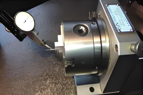
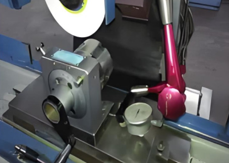
Clamp the workpiece by its 4 mm diameter section in the universal dividing head. To minimize alignment errors, use the 0.372 mm diameter section at the far end as a reference for dial indicator measurements. Rotate the dividing head spindle and adjust the concentric positioning screws to control the runout of the 0.372 mm section to within 0.002 mm.
Dividing Head Positioning
Place the dividing head on the surface grinder’s magnetic table. Attach a dial indicator to the grinding wheel guard, with the indicator tip contacting the right side of the dividing head’s base. Zero the indicator, then adjust the dividing head’s position by moving the grinder’s longitudinal handle to align the dividing head’s axis parallel to the grinder’s longitudinal movement. This ensures parallelism between the dividing head’s axis, the workpiece axis, and the grinding wheel axis. Secure the dividing head to the magnetic table.
Worktable Adjustment
Adjust the grinder’s worktable transversely (X-axis) to position the workpiece axis close to the grinding wheel’s plumb plane, slightly offset toward the wheel’s exit direction. Lock the X-axis and move the worktable longitudinally (Y-axis) until the grinding wheel’s outer edge is near the 4 mm section’s end face. Zero the Y-axis digital display.
Grinding Execution
Rotate the dividing head at 70–80 rpm to ensure uniform workpiece rotation. Start the grinding wheel, maintaining a cutting speed of 35 m/s. Adjust the grinder’s vertical (Z-axis) handle to initiate cutting, controlling the depth of cut to 0.001–0.002 mm per pass. Monitor grinding sound and sparks to assess material removal.
Cylindricity Control
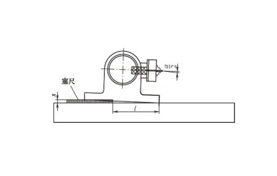
Since top clamping is not feasible, frequent measurements are necessary to control cylindricity. Grinding forces typically cause a slight taper, with the far end being smaller due to deflection. However, for very small diameters, the grinding wheel’s rotational suction may increase material removal at the far end. To correct taper, measure the dimensional difference (a) between the rod’s ends and adjust by placing feeler gauges under the dividing head, as shown below:
| パラメータ | 説明 | Value |
|---|---|---|
| Feeler Gauge Thickness (x) | Calculated based on dimensional difference (a) and grinding length (12 mm) | x = a / (2 × 12) |
| Feeler Gauge Placement | Length of feeler gauge inserted under dividing head | Approximately 15 mm |
Place two sets of feeler gauges for stability, ensuring they are not inserted too deeply. Continue grinding until the rod achieves the specified dimensions and zero taper.
Operational Considerations
To ensure consistent quality and prevent damage, adhere to the following guidelines:
- Rotation Direction: The workpiece and grinding wheel must rotate in the same direction to minimize vibration and ensure smooth cutting.
- Startup and Shutdown: Start workpiece rotation before the grinding wheel and stop it after the wheel stops to prevent surface damage.
- Measurement Timing: Retract the worktable (Y-axis) only after the grinding wheel stops to avoid accidental contact. Measure gently to prevent bending or breaking the workpiece.
- Cylindricity Monitoring: Measure both ends of the rod simultaneously to detect dimensional differences (a) and adjust accordingly.
- Feeler Gauge Adjustment: Calculate feeler gauge thickness based on the formula x = a / (2 × 12), where 12 mm is the grinding length. Use two sets of gauges for stability, inserted approximately 15 mm.
Results and Validation
This method has been successfully applied to machine nearly 1,000 coaxial precision rods, consistently meeting dimensional accuracy, geometric tolerances, and 表面仕上げ requirements. The process provides a reliable alternative to cylindrical grinding for small-diameter, high-precision rods, particularly when conventional methods are impractical.
結論
Using a small precision surface grinder with a universal dividing head offers a robust solution for machining coaxial precision rods with small diameters and stringent coaxiality requirements. By carefully preparing the machine, workpiece, and grinding wheel, and following a systematic machining process with precise alignment and measurement, manufacturers can achieve high-quality results. This method demonstrates the adaptability of existing equipment to address complex machining challenges, providing a practical and effective approach for producing critical components in specialized gauges.