In aircraft manufacturing, similar structural components often lead to mix-ups during production and assembly, resulting in product scrapping, delayed deliveries, and increased costs. This document outlines a systematic error-proofing process to address these issues, implemented during the design, production, and management stages. The methods described ensure clear identification and differentiation of similar components, reducing errors and enhancing manufacturing reliability.
Design Stage: Preventing Mix-Ups Through Component Consolidation and Feature Differentiation
During the design phase, proactive measures are critical to minimize the risk of mix-ups. The process involves reviewing designs to identify and address potential similarities that could lead to errors. Two primary methods are employed: component consolidation and feature differentiation.
Component Consolidation
Component consolidation reduces the number of similar parts by merging them where feasible. During the design review process, engineers evaluate all components to identify those with similar structures or functions. Consolidation is recommended in the following cases:
- Components with identical design structures and geometric tolerances located in different aircraft sections.
- Components with identical or nearly identical design structures where geometric tolerances are within 1/10 to 1/5 of the model’s general tolerance specifications.
By consolidating these components into a single design, the variety of parts is reduced, simplifying inventory management and minimizing the risk of mix-ups. For example, if two components in different wing sections share identical structural properties, they can be merged into a single part number, provided structural and assembly requirements are met.
Feature Differentiation
When consolidation is not feasible due to structural constraints, feature differentiation is applied. This method introduces distinct physical characteristics to similar components to make them easily identifiable. Differentiation can be achieved through modifications such as:
- Chamfering edges at different angles or locations.
- Adding or modifying inner/outer fillets, ribs, bosses, recesses, or cavity structures.
- Adjusting hole positions or spacing.
These modifications ensure that components are visually and physically distinct, reducing the likelihood of confusion during production or assembly. For instance, a rib added to one component but not another provides a clear tactile and visual cue for differentiation.
Production Stage: Identifying Similar Components
In the production stage, where components are manufactured and assembled, the risk of mix-ups increases due to the physical similarity of parts. To address this, specific identification methods are implemented, including process hole identification and production scheduling differentiation.
Process Hole Identification
Process hole identification leverages hole patterns to distinguish similar components. This method is particularly effective for components with high structural similarity, as it uses predefined hole characteristics to create identifiable differences.
Principles for Process Hole Selection
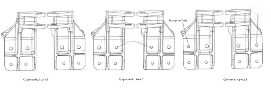
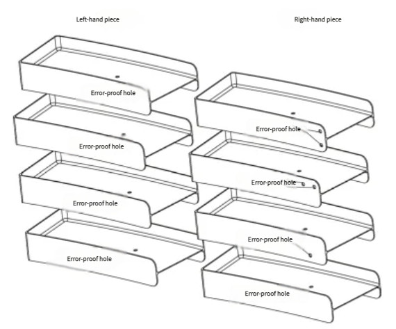
Process holes are strategically placed to differentiate components. For symmetric components, process holes are designed with symmetry to maintain consistency while ensuring differentiation. The following principles guide process hole selection:
- Holes are placed in distinct locations to differentiate similar components.
- For symmetric components, process holes are symmetrically positioned to avoid confusion between left and right parts.
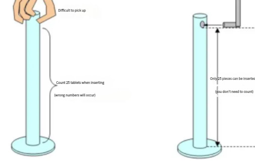
- For components with installation holes, preliminary process holes are created during machining, with diameters smaller than the final hole size (e.g., fb < fa, where fa is the final hole diameter).
For example, consider a batch of components with installation holes of final diameter fa. One or more holes (n, where 1 ≤ n ≤ N, and N is the total number of installation holes) are designated as process holes with diameter fb (fb < fa). The remaining holes (N-n) are machined to either the final diameter fa or an intermediate diameter fc (fc < fa, fc ≠ fb). During assembly, the process holes (fb) are machined to the final diameter (fa). This method ensures clear identification during production.
| Component Type | Process Hole Diameter | Final Hole Diameter | Identification Method |
|---|---|---|---|
| With Installation Holes | fb (fb < fa) | fa | Pre-machined process holes at distinct locations |
| Without Installation Holes | fd (fd < fe) | fe | Pre-machined rivet process holes based on hole center coordinates |
Process Hole Identification for Components Without Installation Holes
For components that lack installation holes in their initial state (e.g., holes appear only during assembly as rivet holes), preliminary rivet holes are created. The process involves:
- Extracting hole center coordinates for pre-machined rivet holes.
- Transferring coordinates using a medium (e.g., supply state data) and coordinating with relevant units.
- Creating a process digital model based on hole coordinates and component geometry, used as the basis for manufacturing components with rivet process holes.
- Assigning a unique identifier to the process digital model (e.g., part number + version + GS + process model version).
For example, a component without installation holes may have n process holes (1 ≤ n ≤ N, where N is the number of rivet holes in the assembled state) with diameter fd (fd < fe, where fe is the final rivet hole diameter). The remaining holes are machined to either fe or an intermediate diameter ff (ff < fe, ff ≠ fd). During assembly, the process holes (fd) are machined to the final diameter (fe).
Production Scheduling Differentiation
To further reduce mix-ups, production scheduling is optimized to separate the manufacturing of similar or symmetric components. Manufacturing units create a detailed list of similar and symmetric components and schedule their production in distinct batches or time periods. This ensures that similar components are not processed simultaneously, reducing the risk of confusion during handling or storage.
Management Stage: Differentiating Similar Components
In the management stage, additional methods are employed to ensure clear identification of similar components, particularly during inspection and final assembly. These methods include hardness testing point differentiation and permanent marking.
Hardness Testing Point Differentiation
について metal components, hardness testing point differentiation uses the location of hardness test indentations to distinguish similar parts. Indentations are typically not covered by surface coatings or plating, making them a reliable identification method. Process engineers specify distinct hardness testing locations in manufacturing instructions, ensuring compliance with hardness testing standards. Inspectors and testers follow these instructions to maintain consistency and avoid mix-ups.
Permanent Marking
Permanent marking provides a robust method for component identification. Two approaches are used:
Permanent Indelible Marks
If permitted by design specifications, components are marked with indelible identifiers immediately after machining. These marks, such as vibration pen markings, etched symbols, or metal stamps, are resistant to subsequent processing steps. The marks are placed in designated areas to ensure visibility and durability.
Removable Permanent Marks
For components where permanent marks are not allowed, temporary features like process bosses or lugs are added. These features carry identification marks and are removed before final delivery, with any necessary surface treatments (e.g., repainting) applied. The location and form of these features are determined by the manufacturing workshop, and they may be applied to all components in a batch or a single representative component.
| Marking Type | Application | Removal Requirement | ユースケース |
|---|---|---|---|
| Permanent Indelible Marks | Post-machining, in designated areas | Not required | Components allowing surface marks |
| Removable Permanent Marks | Process bosses or lugs | Required before delivery | Components prohibiting permanent marks |
結論
について error-proofing process outlined addresses the challenges of mix-ups in aircraft manufacturing by implementing systematic measures across the design, production, and management stages. Component consolidation and feature differentiation reduce part variety and enhance identifiability during design. Process hole identification and production scheduling differentiation ensure clear distinction during manufacturing. Hardness testing point differentiation and permanent marking provide robust identification during inspection and assembly. These methods, grounded in practical application and technical precision, are applicable to both development and batch production of various aircraft models, ensuring reliability and efficiency in manufacturing processes.