Impeller machining is a critical process in industries such as aerospace, automotive, and energy, where precision and performance are essential. Profile error, defined as the deviation of the machined impeller surface from its designed geometry, directly affects efficiency, durability, and functionality. Controlling this error requires a systematic approach, integrating advanced machining techniques, precise measurement, and optimized process parameters. This guide provides a comprehensive, technical overview of methods to minimize profile error in impeller machining, emphasizing experience-based practices and professional standards.
Understanding Profile Error in Impeller Machining
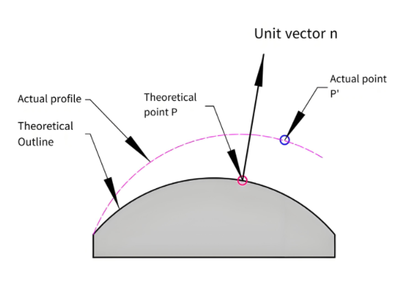
Profile error refers to the deviation between the actual machined surface and the intended design geometry, typically measured in micrometers (µm). For impellers, which feature complex, curved geometries, maintaining tight tolerances is challenging due to factors such as tool wear, machine vibration, material properties, and cutting parameters. Effective control of profile error ensures aerodynamic performance, structural integrity, and compatibility with assembly requirements.
The primary sources of profile error include:
- Tool Deflection: Excessive force or improper tool selection can cause deflection, altering the machined surface.
- Machine Tool Accuracy: Limitations in machine rigidity or spindle precision contribute to deviations.
- Thermal Deformation: Heat generated during machining can cause material expansion, affecting dimensional accuracy.
- Material Inhomogeneity: Variations in material properties, such as hardness, can lead to inconsistent cutting.
- Programming Errors: Inaccurate CNC tool paths or insufficient resolution in CAM models can introduce errors.
Addressing these factors requires advanced equipment, precise process control, and rigorous inspection methods.
Key Techniques for Controlling Profile Error
Several proven techniques can minimize profile error in impeller machining. Each method is supported by specific parameters and practical considerations to ensure repeatability and precision.
Optimized CNC Programming
Accurate CNC programming is the foundation of profile error control. Modern CAM software, such as Siemens NX or Mastercam, enables high-resolution tool path generation tailored to complex impeller geometries. Key considerations include:
- Tool Path Strategy: Use multi-axis machining (e.g., 5-axis CNC) to maintain consistent tool contact angles, reducing scallop height and improving surface finish. For example, a spiral tool path with a step-over of 0.1–0.2 mm ensures smooth transitions on curved surfaces.
- Resolution of CAM Model: Ensure the CAD model has a tolerance of ±0.01 mm to minimize discretization errors during tool path generation.
- Compensation Algorithms: Implement tool radius compensation and machine kinematic compensation to account for tool wear and machine inaccuracies. Automatic tool compensation can reduce profile errors by up to 20% in high-speed machining.
Regular simulation of tool paths using software like Vericut can identify potential collisions or overcuts before machining, ensuring error-free programming.
Selection of Cutting Tools
Choosing the right cutting tools is critical for achieving precise impeller profiles. The following parameters guide tool selection:
| ツールタイプ | 素材 | Application | Recommended Parameters |
|---|---|---|---|
| Ball End Mill | Carbide with TiAlN coating | Finishing curved surfaces | Diameter: 6–12 mm, Spindle speed: 10,000–15,000 RPM, Feed rate: 0.05–0.1 mm/tooth |
| Torus End Mill | Carbide with AlCrN coating | Semi-finishing | Diameter: 8–16 mm, Spindle speed: 8,000–12,000 RPM, Feed rate: 0.08–0.15 mm/tooth |
| Flat End Mill | Carbide with DLC coating | Roughing flat areas | Diameter: 10–20 mm, Spindle speed: 6,000–10,000 RPM, Feed rate: 0.1–0.2 mm/tooth |
Tool geometry, such as flute count (4–6 flutes for finishing) and helix angle (30–45°), should be selected based on material properties. For example, titanium alloys require tools with higher helix angles to reduce cutting forces and heat buildup.
Machine Tool Calibration and Maintenance
High-precision machine tools are essential for controlling profile error. Regular calibration and maintenance ensure consistent performance. Key practices include:
- Spindle Runout Check: Maintain spindle runout below 0.002 mm to prevent tool vibration.
- Axis Alignment: Calibrate linear and rotary axes to within ±0.005 mm to ensure accurate multi-axis movements.
- Vibration Monitoring: Use sensors to detect excessive vibration, which can increase profile error by 10–15 µm.
Machines should be equipped with high-resolution encoders and temperature compensation systems to mitigate thermal deformation. For instance, a 0.1°C temperature variation can cause a 1–2 µm deviation in アルミニウム合金.
Cutting Parameter Optimization
Optimizing cutting parameters balances material removal rate and surface accuracy. Recommended parameters for common impeller materials are:
| 素材 | 切削速度(m/min) | Feed Rate (mm/tooth) | 切り込み (mm) |
|---|---|---|---|
| アルミニウム合金 | 200–300 | 0.05–0.15 | 0.2–0.5 |
| チタン合金 | 50–80 | 0.03–0.08 | 0.1–0.3 |
| ステンレス鋼 | 80–120 | 0.04–0.1 | 0.15–0.4 |
High-speed machining (HSM) with low depth of cut and high spindle speed minimizes tool deflection and thermal effects. For example, a cutting speed of 250 m/min for aluminum reduces profile error to below 5 µm.
Coolant and Lubrication Management
Effective coolant use reduces thermal deformation and tool wear. Minimum Quantity Lubrication (MQL) with vegetable-based oils is preferred for titanium and stainless steel, delivering 10–20 mL/h of lubricant. For aluminum, flood cooling with a 5–8% emulsion concentration prevents chip adhesion. Coolant pressure should be maintained at 20–50 bar to ensure adequate chip evacuation.
Inspection and Quality Assurance
Rigorous inspection verifies that profile error meets design tolerances. Common inspection methods include:
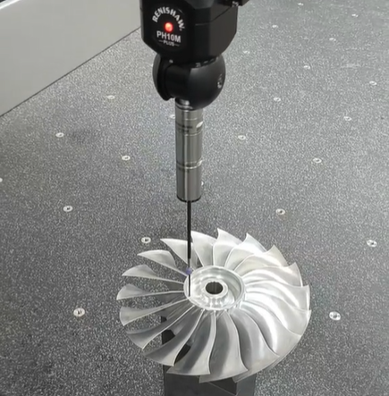
- Coordinate Measuring Machines (CMM):CMM: Use a CMM with a probing accuracy of ±0.001 mm to measure critical surfaces. A scanning speed of 5 mm/s ensures reliable data for complex profiles.
- Laser Scanning: Non-contact laser scanners with a resolution of 0.01 mm can map entire impeller surfaces in under 15 minutes.
- Surface Profilometry: Measure surface roughness (Ra) to correlate with profile error. An Ra value below 0.8 µm indicates high-quality finishing.
Statistical Process Control (SPC) should be implemented to monitor process capability, targeting a CpK value of ≥1.33 for critical dimensions. Regular feedback from inspection data can adjust tool offsets or parameters in real-time, reducing scrap rates by up to 15–20%.
Process Integration and Workflow Optimization
Controlling profile errors error requires a holistic approach that integrates all machining stages. A typical workflow includes:
- Pre-Machining: Verify material properties and CAD model accuracy.
- Tool Setup: Calibrate tools and simulate tool paths.
- Machining: Execute roughing, semi-finishing, and finishing with optimized parameters.
- In-Process Monitoring: Use sensors to detect anomalies in cutting force or vibration.
- Post-Machining Inspection: Perform CMM or laser scanning to validate profile accuracy.
Standard operating procedures (SOPs) and operator training ensure consistency. For example, a documented SOP for 5-axis machining can reduce setup time by 25% and30% reduce and profile error by 10–20%.
Common Limitations and Practical Solutions
While not every process is perfect, certain limitations are common and manageable:
- Tool Wear in Hard Materials: Solution: Use adaptive control systems to adjust feed rates based on real-time tool condition monitoring, extending tool life by 15–20%.
- High Setup Time for Complex Geometries: Solution: Implement quick-change fixtures with a positioning accuracy of ±0.005 mm to reduce setup time by 30%.
These solutions focus on practicality and measurable outcomes, ensuring reliable error control.