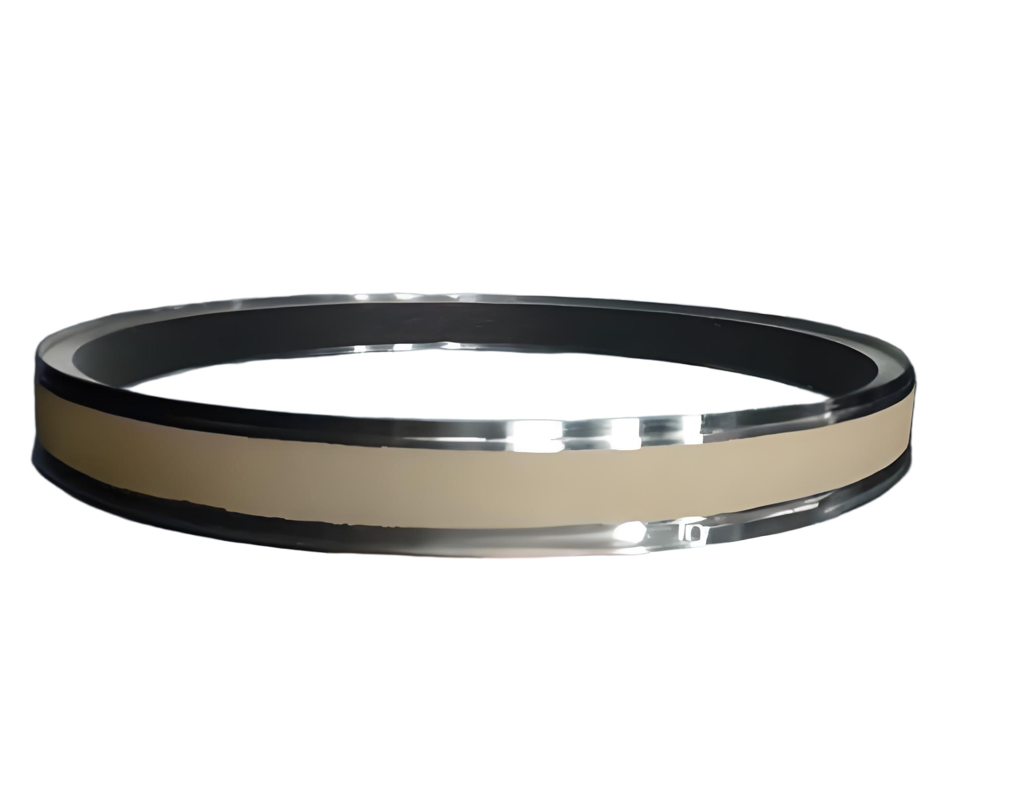
The honeycomb inner ring component, a critical part of aero-engines, is composed of a main ring and an internal honeycomb ring welded together. Its complex structure, thin walls, susceptibility to deformation, difficult-to-machine materials, and high dimensional accuracy requirements pose significant challenges in manufacturing. The main ring is made of AMS5665 nickel-based high-temperature alloy, while the honeycomb ring is crafted from AMS5536 nickel-based corrosion-resistant and heat-resistant alloy subjected to solution heat treatment. Controlling machining deformation is pivotal to ensuring part quality, improving yield rates, reducing costs, and enhancing competitiveness. This article systematically explores deformation causes, process strategies, clamping designs, and programming optimizations based on experimental research to address these challenges.
Component Materials and Structural Characteristics
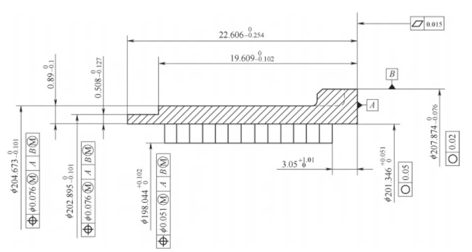
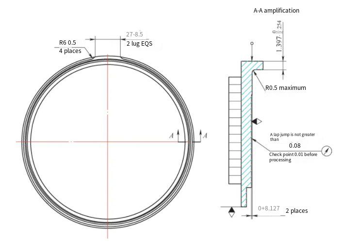
The honeycomb inner ring component is a rotational part with a maximum outer diameter of 207.874 mm and a total height of 22.606 mm. It demands a roundness tolerance of 0.02 mm and a minimum wall thickness of 0.508 mm. The outer diameter’s positional tolerance relative to the datum is 0.076 mm. The inner bore, formed by the brazed honeycomb ring, has a diameter of 198.044 mm. The component features two circumferentially distributed bosses on the rear end, each measuring 24.994 mm, flanked by relief grooves (25.4 mm long, 3.81 mm wide, 0.127 mm deep). The radial step between the boss and the outer diameter, as well as between the relief groove and the boss, must not exceed 0.127 mm.
The material, AMS5665, is a high-strength, high-hardness nickel-based alloy with excellent high-temperature performance but poor machinability due to high viscosity and low thermal conductivity. This leads to significant cutting forces and heat generation, accelerating tool wear if heat dissipation is inadequate. The AMS5536 honeycomb ring, with its hexagonal grid structure, adds complexity due to its brazed integration and thin-walled nature.
Key structural characteristics include:
- High Precision Requirements: Inner bore roundness of 0.05 mm, outer diameter roundness of 0.02 mm, and rear face flatness of 0.015 mm.
- Poor Rigidity: Wall thickness ranges from 0.508 to 0.89 mm, resulting in low structural stiffness.
- Poor Processability: Tight tolerances for boss and relief groove steps (≤0.127 mm) and lack of reliable clamping datums contribute to deformation during machining and clamping.
Causes of Machining Deformation
Deformation in machining thin-walled components like the honeycomb inner ring arises from multiple factors, including material properties, geometric structure, machining processes, clamping methods, and programming strategies. Understanding these causes is essential for developing effective control measures.
素材の特性: The high hardness and viscosity of AMS5665 and AMS5536 result in poor machinability. Cutting forces required to overcome elastic and plastic deformation, combined with friction between the tool and workpiece, generate substantial cutting heat. Uneven temperature distribution across the part causes thermal deformation.
Geometric Structure: The thin walls (0.508–0.89 mm) and uneven wall thickness of the forged blank lead to varying rigidity across sections. Under cutting forces, sections with lower rigidity deform more, causing dimensional and roundness errors.
Cutting Forces: The forces exerted by the tool induce plastic deformation on the part’s surface, particularly in thin-walled regions, exacerbating dimensional inaccuracies.
Clamping Methods: Improper selection of clamping datums or excessive clamping forces introduces additional stresses, leading to elastic or plastic deformation. Radial clamping, often used in soft jaw setups, can either be insufficient for rough machining or excessive, causing deformation in thin-walled parts.
Process Parameters: Inappropriate feed paths or cutting parameters in turning and milling operations can induce vibrations, leading to dimensional inaccuracies and poor surface quality.
Equipment and Environment: The rigidity of machine tools, fixturing systems, ambient temperature, and cooling conditions also influence deformation, though to a lesser extent.
Process Strategies for Deformation Control
Controlling deformation is critical to achieving the required precision and avoiding issues such as loss of clamping datum or insufficient machining allowance, which can lead to part rejection. The following strategies were developed to address deformation:
Material Selection: Using forged rings with precipitation treatment and stress relief minimizes residual stresses in the blank, enhancing rigidity during rough machining and improving roundness control.
Clamping Design: Specialized turning and milling fixtures were designed to reduce clamping-induced deformation. For turning, a self-centering chuck is used for rough machining of the outer diameter, while soft jaws are employed for machining end faces and inner/outer profiles. Axial clamping replaced radial clamping to improve roundness stability, achieving inner bore roundness of 0.03–0.07 mm before brazing, meeting design requirements.
Process Sequencing: Rough turning removes large material allowances to minimize initial deformation, followed by semi-finishing and finishing stages with reduced cutting depths (1.0 mm for roughing, 0.5 mm for semi-finishing, 0.2 mm for finishing) to control deformation incrementally.
Fixture Rigidity: Fixtures were designed to enhance part support, particularly for thin-walled sections, reducing vibration and deformation during machining.
Fixture Design for Precision Machining
Fixture design plays a pivotal role in minimizing clamping-induced deformation and ensuring machining accuracy. The following details outline the fixture designs for turning and milling operations.
Turning Fixtures: For finish turning, the left end face and inner bore serve as primary and secondary datums, respectively. A central pressure plate and nut secure the part axially, reducing radial stresses. The fixture’s mandrel is aligned to ensure concentricity with the part’s inner bore, achieving a roundness of 0.03–0.07 mm pre-brazing. Post-brazing, the fixture supports the part’s right-end inner bore to enhance rigidity, minimizing deformation during finish turning. The fixture body and pressure plate are machined to maintain concentricity within 厳しい公差, ensuring stable clamping and minimal part movement.
Milling Fixtures: For milling the outer profile, initial attempts using inner bore clamping resulted in poor outer diameter roundness and significant radial runout. A revised approach used the machined end face and outer diameter for positioning. A milling fixture with an inner bore matched to the part’s outer diameter (gap of 0.02–0.05 mm) and a central pressure plate was developed. Coordinate measuring machine (CMM) inspections ensured concentricity between the fixture’s bore and pressure plate, maintaining part roundness during milling.
Programming Optimization for Machining
Optimized programming is critical for controlling deformation and achieving dimensional accuracy. Separate strategies were developed for turning and milling operations.
Turning Programming: Finish turning uses a 35° VCMT160402-SM diamond-shaped insert to minimize tool wear and ensure sharp cutting edges. The process involves removing deformation from rough machining, followed by finish turning with a cutting depth of 0.2 mm, a linear speed of 30 m/min, and a feed rate of 0.1 mm/rev. A deburring step in the final pass reduces manual finishing time. This approach increased the roundness qualification rate from 20–25% to 100%. For outer profile turning, a three-stage process (roughing at 1.0 mm depth, semi-finishing at 0.5 mm, finishing at 0.2 mm) achieved radial runout of 0.01–0.02 mm after roughing and ≤0.01 mm after finishing, with roundness within 0.10 mm per CMM inspection.
Milling Programming: Initial milling with a bar-shaped cutter caused excessive cutting forces, leading to deformation and radial runout. A T-shaped φ10 mm dedicated milling cutter was adopted, operating at 300 rpm with a feed rate of 0.02 mm/tooth. Circular interpolation was used for tool entry and exit to minimize cutting forces. This reduced radial runout to 0.05–0.10 mm during clamping and ≤0.12 mm post-machining, ensuring step dimensions met the 0.127 mm requirement. For corner milling, tool paths were refined to maintain consistent cutting angles, with segmented speed reductions to eliminate chatter and improve surface quality.
Experimental Results and Validation
Experimental trials validated the effectiveness of the proposed strategies. The turning fixture design and axial clamping approach achieved inner bore roundness of 0.03–0.07 mm pre-brazing, meeting design specifications. Milling fixture redesign reduced outer diameter radial runout and ensured step dimensions within 0.127 mm. Optimized turning and milling programs eliminated chatter, improved surface quality, and increased the qualification rate to 100%. CMM inspections confirmed that dimensional tolerances, roundness, and flatness requirements were consistently met.
The following table summarizes key machining parameters and outcomes:
| Operation | Tool | Cutting Depth (mm) | フィード・レート | Outcome |
|---|---|---|---|---|
| Finish Turning (Inner Bore) | VCMT160402-SM | 0.2 | 0.1 mm/rev | Roundness 0.03–0.07 mm, 100% qualification |
| Finish Milling (Outer Profile) | T-shaped φ10 mm | - | 0.02 mm/tooth | Radial runout ≤0.12 mm, step ≤0.127 mm |
結論
The machining of honeycomb inner ring components requires careful consideration of material properties, structural characteristics, clamping methods, and programming strategies to control deformation. By selecting stress-relieved forged blanks, designing rigid and precise fixtures, and optimizing turning and milling programs, deformation was effectively minimized. The inner bore roundness was controlled within 0.03–0.07 mm, outer diameter roundness within 0.10 mm, and step dimensions within 0.127 mm, meeting all design requirements. These strategies provide a robust technical foundation for machining similar thin-walled, high-precision aero-engine components, improving quality, yield, and cost-efficiency.