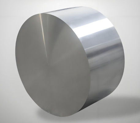
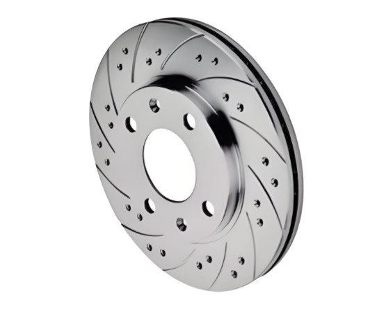
Silicon carbide reinforced aluminum matrix composites (SiC/Al) are widely used in high-performance applications such as satellite bearings, laser reflectors, and inertial gyroscopes due to their excellent thermal stability and micro-yield strength. However, machining these materials poses significant difficulties due to the hard SiC particles embedded in the softer aluminum matrix. These particles cause issues such as particle dissociation, fracture, and pull-out, leading to defects like cracks and poor surface quality. This article provides a detailed, systematic approach to addressing these machining challenges through material cutting mechanism analysis, tool selection, optimized cutting parameters, and specialized thread machining techniques.
Material Characteristics and Machining Challenges
SiC/Al composites are classified as difficult-to-machine materials due to the high hardness of SiC particles (3000–3500 HV), which are dispersed within the aluminum matrix. These particles act similarly to abrasive grains in a grinding wheel, causing severe tool wear through abrasion and impact on the cutting edge. The higher the SiC content, particle size, and volume fraction, the faster the tool wear and the more pronounced the particle dissociation. During machining, SiC particles may fracture, dissociate, or pull out, leading to surface cracks and defects, as shown in experimental results. Traditional machining knowledge for homogeneous materials is not directly applicable, necessitating specific cutting trials to understand the material’s behavior.
Key challenges include:
- Rapid tool wear due to abrasive SiC particles.
- Surface defects caused by particle dissociation and pull-out.
- Poor surface finish and dimensional accuracy in high-precision applications.
- Difficulty in achieving consistent tool life and machining efficiency.
These issues require careful selection of tool materials, cutting parameters, and machining strategies to ensure quality and efficiency.
Tool Material Selection
Selecting the appropriate tool material is critical for machining SiC/Al composites. Cutting trials reveal that conventional tools, such as YW3 cemented carbide, suffer severe abrasive wear when machining SiC/Al with 16–18% SiC content. Tool life is reduced to less than one-third compared to machining carburized cast iron under similar conditions. When machining higher SiC content (40–42%), wear accelerates further. Coated carbide tools also fail quickly, as the hard SiC particles abrade the coating and expose the carbide substrate, leading to rapid tool degradation.
Diamond tools, particularly polycrystalline diamond (PCD) and chemical vapor deposition (CVD) thick-film diamond (TFD), are the most effective for machining SiC/Al composites. Diamond offers:
- High hardness and wear resistance, maintaining sharp cutting edges.
- Low friction coefficient, reducing adhesion and built-up edge formation.
- High thermal conductivity, dissipating heat effectively.
- Superior surface finish, achieving roughness values as low as Ra 0.8 μm.
Cutting trials with 40% SiC/Al composites under conditions of 40 m/min cutting speed, 0.05 mm/rev feed rate, and 0.5 mm depth of cut show that TFD diamond tools exhibit the lowest wear, followed by coarse-grain PCD025, while fine-grain PCD002 has the shortest lifespan. Coarse-grain PCD025 is suitable for roughing due to its high fracture toughness, while TFD and single-crystal diamond tools excel in semi-finishing and finishing due to their ability to maintain edge sharpness.
| 工具材料 | Wear Characteristics | Suitable Application |
|---|---|---|
| TFD Diamond | Lowest wear rate, longest tool life | High-speed finishing, semi-finishing |
| PCD025 (Coarse Grain) | Moderate wear, high fracture toughness | Roughing, high-toughness applications |
| PCD002 (Fine Grain) | Higher wear rate, better surface finish | Finishing with lower toughness requirements |
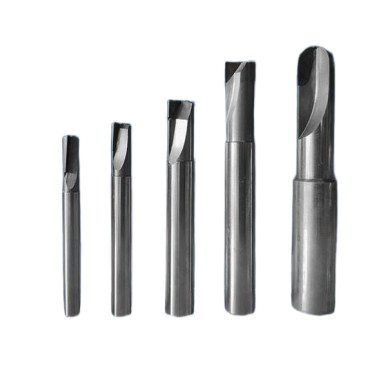
Optimizing Tool Geometry
Tool geometry significantly affects cutting forces, tool life, and surface quality. Cutting trials demonstrate that increasing the rake angle reduces the main cutting force, minimizing SiC particle dissociation and crack formation. However, a larger relief angle, while reducing cutting forces by facilitating easier cutting, accelerates tool wear and shortens tool life. Optimal geometry for turning SiC/Al composites includes:
- Rake Angle: 3°–6°, balancing cutting force reduction and tool durability.
- Relief Angle: 5°–8°, ensuring easy cutting while maintaining edge strength.
For milling, small helix angle PCD or CVD end mills (less than 10°) are recommended. High helix angles increase the separation of SiC particles under cutting forces, degrading surface quality. Low helix angles reduce this effect, improving surface finish and dimensional accuracy.
Optimizing Cutting Parameters
Cutting parameters directly influence tool life, surface quality, and machining efficiency. Diamond tool performance is affected by cutting speed, feed rate, and depth of cut. Key findings from cutting trials include:
- 切断速度: Higher speeds (40–120 m/min) improve surface finish but increase cutting temperature and particle dissociation if not properly cooled. Optimal turning speeds range from 20–40 m/min, while milling speeds of 10–40 m/min (spindle speeds of 530–2123 rpm) yield smooth surfaces.
- フィードレート: Lower feed rates (e.g., 0.02–0.09 mm/rev) reduce surface roughness and particle pull-out. For turning, 0.09 mm/rev is effective, while milling benefits from 0.02 mm/rev.
- カットの深さ: A depth of 0.5 mm is suitable for both turning and milling, as deeper cuts (e.g., 1.5 mm) increase vibration, particle pull-out, and surface defects.
- Coolant: Kerosene-based or TONC550-2 emulsified cutting fluids enhance tool life and surface quality by reducing cutting temperatures. Continuous coolant supply is critical to prevent tool damage from thermal shock.
High cutting parameters (e.g., 130 m/min speed, 1.5 mm depth, 0.05 mm/rev feed) result in excessive vibration, particle pull-out, and defects like pits and cracks. Optimized parameters ensure a bright, smooth surface with minimal defects.
| Operation | 切削速度(m/min) | 送り速度(mm/rev) | 切り込み (mm) | Coolant |
|---|---|---|---|---|
| ターニング | 20–40 | 0.09 | 0.5 | Kerosene-based or TONC550-2 |
| ミーリング | 10–40 (530–2123 rpm) | 0.02 | 0.5 | Kerosene-based or TONC550-2 |
Thread Machining Optimization
Machining internal threads (e.g., M16×1) in SiC/Al composites is particularly challenging due to the material’s brittleness. Cutting forces and stress concentration at the thread entry and exit cause crest chipping, resulting in serrated thread profiles. This can lead to debris generation during thread engagement, compromising component safety and performance in critical applications like nozzle assemblies.
An optimized thread machining sequence was developed through trials:
- Turn the thread bore.
- Chamfer the bore edge.
- Turn the thread.
- Cut the relief groove.
- Chamfer the thread exit.
Using a forming tool to create chamfers reduces crest chipping by minimizing stress concentration. Post-machining, a custom thread crest scraper (designed for internal threads) is used to manually remove burrs and smooth serrated crests, ensuring compliance with design specifications. This approach improves thread quality and eliminates debris-related risks.
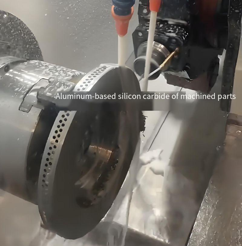
Practical Implementation and Results
The optimized machining strategy was applied to batch production of inertial gyroscopes and damping plates. Using diamond tools (TFD for finishing, PCD025 for roughing), optimized tool geometry (3°–6° rake, 5°–8° relief), and recommended cutting parameters (20–40 m/min speed, 0.02–0.09 mm/rev feed, 0.5 mm depth), the following results were achieved:
- Smooth, bright machined surfaces with roughness values as low as Ra 0.8 μm.
- Extended tool life, with diamond tools lasting several times longer than carbide tools.
- Consistent dimensional accuracy meeting technical specifications.
- Elimination of surface defects like cracks and particle pull-out pits.
Continuous coolant application and careful process control (avoiding interruptions or parameter changes during cutting) were critical to maintaining tool integrity and surface quality. This approach ensured economic efficiency and successful completion of production tasks for high-precision components.
結論
Machining SiC/Al composites requires a systematic approach addressing the material’s unique challenges. Diamond tools, particularly TFD and PCD, are essential for achieving long tool life and high surface quality. Optimized tool geometry (3°–6° rake, 5°–8° relief for turning; low helix angles for milling) and cutting parameters (20–40 m/min speed, 0.02–0.09 mm/rev feed, 0.5 mm depth) minimize defects and ensure efficiency. Specialized thread machining sequences and post-processing techniques further enhance quality for critical applications. These strategies, validated through extensive cutting trials, provide a reliable framework for machining SiC/Al composites in high-precision industries.