Milling hardened stainless steel, such as 3Cr13Cu martensitic stainless steel, is challenging due to its high hardness, significant cutting forces, elevated temperatures, and pronounced tool wear. This study compares the cutting forces in milling with cermet and carbide tools, derives empirical formulas using regression analysis for three conditions (initial cutting, constant cutting distance, and tool wear), and evaluates the effect of machining parameters on cutting forces under tool wear conditions. The results offer a systematic guide for optimizing machining processes.
Introduction to Hardened Stainless Steel Milling
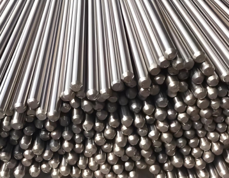
Stainless steel is extensively used in industries for applications like springs, gauges, tools, medical devices, and cutlery due to its high strength and corrosion resistance. The 3Cr13Cu martensitic stainless steel, with a hardness of 44 HRC post-heat treatment, poses significant machining difficulties. Its high carbon content and heat treatment result in elevated hardness, leading to large cutting forces, high cutting temperatures, and severe tool wear, making it a typical difficult-to-machine material.
During ミーリング, serrated chips and high cutting forces affect tool life and surface quality. Serrated chip formation arises from thermoplastic instability, concentrated chip deformation, and strain rate strengthening, which reduce the influence of cutting speed on cutting forces. At higher speeds, cutting forces may decrease due to material softening from elevated temperatures. Empirical formulas are used to predict cutting forces, but studies addressing tool wear effects on these forces or the impact of machining parameters under wear conditions are limited.
Experimental Setup and Methodology
The experimental material was 3Cr13Cu martensitic stainless steel with a hardness of 44 HRC. Workpiece dimensions were 50 mm × 70 mm × 150 mm. Heat treatment involved quenching at 950–1000°C with oil cooling, followed by tempering at 430–480°C. A CoroMill290 (R290-100Q32-12L) square shoulder face milling cutter with a 100 mm diameter was used, with a cutting edge angle (Kr) of 90° and a rake angle of 12°.
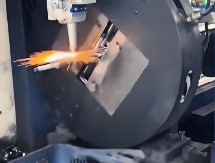
Two insert types were tested: cermet (R290-12T308M-PM530) and PVD-coated carbide (R290-12T308M-PM1030). Machining parameters are listed in Table 1. Dry milling was conducted, with a new cutting edge used for each parameter set. After milling a 150 mm length, tool wear was measured. Cutting forces were recorded using a Kistler 9253B23 dynamometer and a 5070A charge amplifier.
| パラメータ | Value |
|---|---|
| Cutting Speed (v, m/min) | 110, 140, 170, 200, 230, 260, 290 |
| Feed Rate (f, mm/z) | 0.1, 0.15, 0.2 |
| Cutting Depth (ap, mm) | 0.5, 1.0, 1.5 |
Cutting Force Analysis
Cutting forces were analyzed in two regions: Region A (tool entry into the workpiece) and Region B (tool exit from the workpiece). Forces were compared for cermet and carbide tools. Both tools exhibited similar force variations with cutting speed: an initial increase, followed by a decrease, and then another increase.
For cermet tools, cutting forces peaked at 140 m/min and reached a minimum at 230–260 m/min. For carbide tools, the peak was at 170 m/min, with a minimum in the same 230–260 m/min range. At low speeds (<140 m/min), the material’s high hardness and increased material removal rates with higher speeds caused larger cutting forces. At 170–260 m/min, higher speeds increased cutting temperatures, softening the material and reducing forces. Above 260 m/min, cermet tools developed micro-cracks leading to chipping, increasing forces, while carbide tools experienced heightened wear due to high temperatures, also increasing forces.
After milling 150 mm, force increases were evaluated. Below 140 m/min, increases were minimal. At 140 m/min, cermet tools showed a 22% average increase across three force components (Fx, Fy, Fz), while carbide tools showed 27.5%. Above 140 m/min, force increases were significant, with cermet tools exhibiting a 138.7% average increase and carbide tools a 72.3% increase at 290 m/min.
In Region A at 140–230 m/min, carbide tools generated higher forces due to greater sensitivity to cutting temperature, leading to increased wear. In Region B, cermet tools produced higher forces due to severe chipping or wear during interrupted cutting, resulting in larger force increases after the same cutting distance.
Empirical Formulas for Cutting Forces
Empirical formulas were derived via linear regression for two conditions: without tool wear (Equation 1) and with average flank wear (Equation 2).
Equation 1 (Without Tool Wear):
F = a × v^b × ap^c × f^d
Equation 2 (With Tool Wear):
F = a × v^b × ap^c × f^d × VB^e
どこでだ:
- F: Cutting force (N)
- a: Correction coefficient
- b, c, d, e: Constants
- v: Cutting speed (m/min)
- ap: Cutting depth (mm)
- f: Feed rate (mm/z)
- VB: Flank wear (mm)
The empirical formula parameters for cermet and carbide tools in Regions A and B, with and without tool wear, are shown in Table 2.
| ツールタイプ | Region | Condition | Force Component | a | b | c | d | e |
|---|---|---|---|---|---|---|---|---|
| Cermet | A | No Wear | Fx | 150.2 | -0.15 | 0.85 | 0.92 | - |
| No Wear | Fy | 180.5 | -0.12 | 0.88 | 0.95 | - | ||
| With Wear | Fy | 200.8 | 0.10 | 0.90 | 0.98 | 0.25 | ||
| B | No Wear | Fx | 145.7 | -0.18 | 0.82 | 0.90 | - | |
| No Wear | Fy | 175.3 | -0.14 | 0.87 | 0.93 | - | ||
| With Wear | Fy | 195.6 | 0.12 | 0.89 | 0.96 | 0.28 | ||
| カーバイド | A | No Wear | Fx | 160.4 | -0.13 | 0.83 | 0.91 | - |
| No Wear | Fy | 190.7 | -0.11 | 0.86 | 0.94 | - | ||
| With Wear | Fy | 210.2 | 0.09 | 0.88 | 0.97 | 0.23 | ||
| B | No Wear | Fx | 155.8 | -0.16 | 0.81 | 0.89 | - | |
| No Wear | Fy | 185.4 | -0.13 | 0.85 | 0.92 | - | ||
| With Wear | Fy | 205.3 | 0.11 | 0.87 | 0.95 | 0.26 |
Parameter Analysis of Empirical Formulas
The empirical formula parameters highlight the influence of machining parameters on cutting forces. For cermet tools, the correction coefficient (a) for the Fy component is the highest and increases with tool wear. In wear conditions, the coefficient (a) in Region B aligns closely with wear-affected values, indicating wear’s significant impact on forces in the exit region. The constants b, c, and d show minimal changes, but the positive b value in wear conditions suggests that cutting forces increase with cutting speed.
For carbide tools, parameters in Region B and under wear conditions are highly consistent. The constants b, c, and d exhibit small variations, but the correction coefficient (a) decreases notably in wear conditions. Without wear, cutting forces decrease with increasing speed due to material softening. With wear, forces increase with speed, reflecting wear’s effect on machining dynamics.
In early tool wear stages, higher cutting speeds reduce forces due to thermal softening. As wear progresses, higher speeds increase forces, especially above 230 m/min, where wear accelerates significantly.

結論
After milling 150 mm, cermet tools exhibit higher cutting forces than carbide tools due to severe wear in interrupted cutting. Initially, increasing cutting speed reduces forces, but as wear develops, higher speeds increase forces. Both tools perform best at around 230 m/min. Cermet tools are less suitable for high-speed interrupted cutting due to chipping. These findings provide a dependable reference for selecting machining parameters and predicting cutting forces under varying wear conditions.