This article provides a detailed examination of the machining process for a valve body, a critical component in valve systems. By analyzing the original machining process, fixture design, and identified issues, we propose an optimized process route to address positional accuracy problems caused by V-block positioning errors. The valve body discussed is made of HT250 cast iron and processed on a vertical machining center equipped with a fourth-axis rotary table and tailstock. The solution involves adjusting the process route to recalibrate the datum during finishing, ensuring compliance with stringent positional tolerances.
Overview of Valve Body and Its Machining Requirements
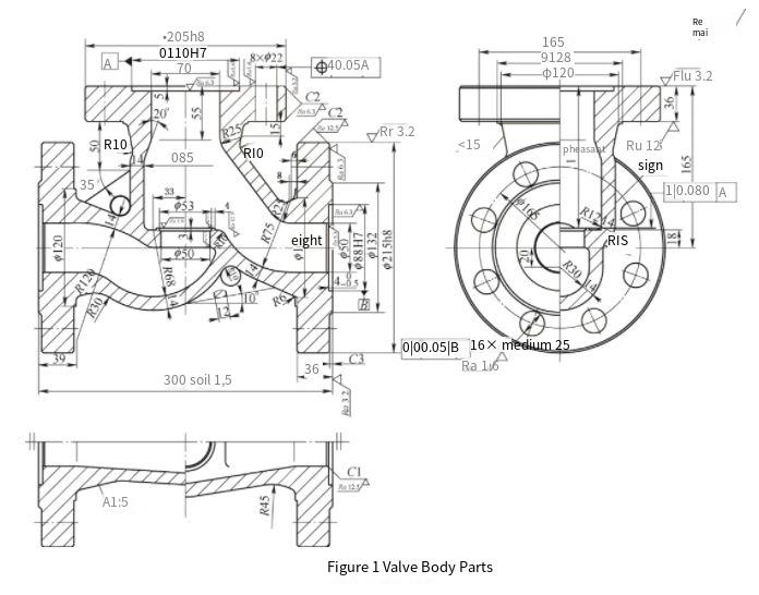
Valve bodies are essential components in valve systems, designed to withstand medium pressure. Typically cast from materials like cast iron, cast steel, or ステンレス鋼, their complex structures demand precise machining to meet technical specifications. The valve body in this case is made of HT250 cast iron, with key features including φ88H7 and φ110H7 bores, φ205h8 and φ215h8 outer diameters, and multiple holes on the outer diameter end faces. The technical requirements are as follows:
- Compliance with GB/T 12229-2005 for castings.
- Annealing treatment for the casting.
- Cast fillet radius of R3–R5 mm unless specified.
- Machining tolerances per GB 1804-79 H14 (h14) js15 for unspecified dimensions.
- Valve seat with E410 overlay, tempered to 33–38 HRC, with a minimum thickness of 2 mm after machining.
- Casting mark per 50J41H-160-01a/A.
について 高精度 required for the φ88H7, φ110H7 bores, and φ205h8, φ215h8 outer diameters makes them critical dimensions. The machining process involves a horizontal lathe, a vertical lathe, and a vertical machining center with a fourth-axis rotary table and tailstock to ensure efficiency and accuracy.
Original Machining Process Route
The original machining process for the valve body was structured to utilize multiple machine tools to achieve the required tolerances. The process is detailed as follows:
- Horizontal Lathe Operations:
- Rough and finish turning of φ215 mm outer diameter and end face.
- Rough and finish boring of φ88H7 bore.
- Turnaround, then rough and finish turning of the opposite φ215 mm outer diameter and end face.
- Rough and finish boring of the second φ88H7 bore.
- Vertical Lathe Operations:
- Rough and finish turning of φ205h8 outer diameter and end face.
- Rough and finish boring of φ110H7 bore.
- Rough turning of φ53 mm bore end face.
- Boring of φ53 mm and φ50 mm bores.
- Vertical Machining Center Operations:
- Rotate table to 90°, drill φ25 mm holes on φ215 mm outer diameter end face with allowance, then finish bore.
- Rotate table to 0°, drill φ22 mm holes on φ205 mm outer diameter end face with allowance, then finish bore.
- Rotate table to -90°, drill φ25 mm holes on φ215 mm outer diameter end face with allowance, then finish bore.
This process relied on the outer diameter centers as datums, with the vertical machining center using V-block fixtures to position the workpiece. While the process was designed for efficiency, it encountered issues with positional accuracy during hole machining.
Fixture Design for Vertical Machining Center
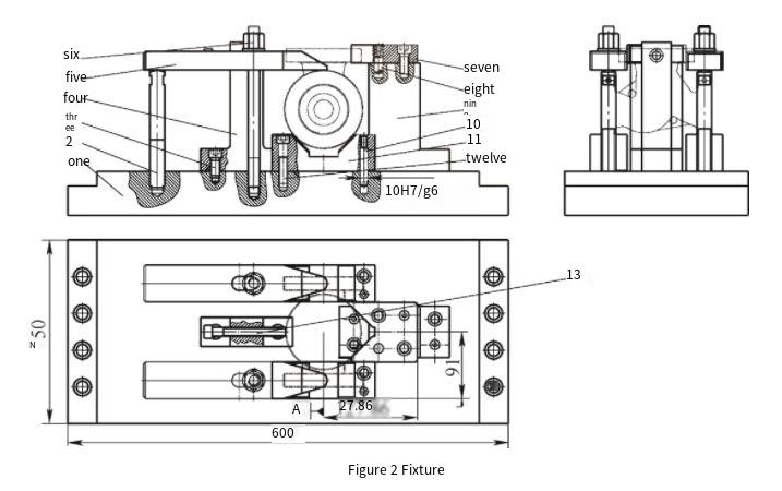
The vertical machining center was tasked with machining holes on three outer diameter end faces. To enhance efficiency, the machine was equipped with a fourth-axis rotary table and tailstock, enabling single-setup machining. The fixture design is critical to ensuring precision and is described below:
- Positioning Datum: The φ215 mm outer diameter center was selected as the primary datum, with V-blocks restricting four degrees of freedom. The φ205 mm outer diameter center was the secondary datum, with V-blocks restricting two degrees of freedom, fully constraining the workpiece.
- Fixture Components:
Component 説明 数量 Fixture Base Supports the entire setup 1 Adjustable Support Pins Provides height adjustment 2 Short Hex Socket Screws Secures components 6 Non-standard Bracket Supports V-blocks 1 Extended Flat Press Plate Clamps workpiece 2 Shoulder Hex Nut & Double-ended Bolt Secures press plates 2 pairs Fixed V-block Positions φ215 mm outer diameter 1 Short Positioning Pins Aligns fixture components 4 Non-standard Support Supports secondary V-block 1 Long Positioning Pins Ensures alignment 4 V-block Positions φ205 mm outer diameter 2 Long Hex Socket Cylindrical Screws Secures V-blocks 4 Hex Socket Clamping Screws Tightens workpiece 2 - Clamping Mechanism: Clamping points were located on the outer diameter surfaces to secure the workpiece during machining.
This fixture design aimed to streamline operations by allowing all hole machining in a single setup, but it introduced challenges related to positional accuracy.
Analysis of Positional Accuracy Issues
During inspection, the machined valve body exhibited positional accuracy issues, specifically with the holes on the outer diameter end faces exceeding the specified positional tolerance of 0.05 mm. The vertical machining center met the JB/T 8771.7-1998 standard, indicating that the machine’s precision was sufficient to achieve the required tolerances. The issue was traced to the fixture design, particularly the V-block positioning.
Positioning errors in fixtures can arise from two sources: datum shift error and datum mismatch error. Analysis of the original process route revealed that the machining operations consistently used the outer diameter centers as datums. For example:
- Horizontal lathe operations used the φ215 mm outer diameter center as the datum for turning and boring.
- Vertical lathe operations used a specialized fixture referencing the outer diameter center for φ205h8 machining.
- The vertical machining center also used the outer diameter centers, with V-blocks as positioning elements.
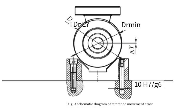
Since the design and positioning datums were aligned, datum mismatch error was ruled out. However, V-block positioning introduced a datum shift error, calculated as ΔY = δd / [2sin(α/2)], where:
- ΔY: Datum shift error.
- δd: Outer diameter tolerance (0.072 mm for φ215 mm).
- α: V-block angle (90°).
Plugging in the values, ΔY = 0.072 / [2sin(45°)] = 0.051 mm. This error exceeded the positional tolerance of 0.05 mm, confirming that the V-block positioning was the primary cause of the positional accuracy issue.
Solutions to Address Positional Accuracy
Three solutions were evaluated to address the positional accuracy issue caused by V-block positioning:
- Modify Fixture Positioning Elements:
Replacing V-blocks with flat positioning surfaces could reduce datum shift error. However, this approach only partially mitigates the issue and does not fully resolve positional accuracy problems, making it an incomplete solution.
- Increase Outer Diameter Precision:
Refining the φ205h8 and φ215h8 outer diameters to φ205h6 and φ215h6 would reduce the diameter tolerance to 0.029 mm, lowering the datum shift error to ΔY = 0.029 / [2sin(45°)] = 0.02 mm. This meets the positional tolerance but increases demands on lathe precision, reduces efficiency, and raises costs. For mass production, maintaining h6 tolerance is challenging, rendering this solution suboptimal.
- Revise Process Route:
The most effective solution involved revising the entire process route to recalibrate the datum during finishing. The design datum was the bore center, so a finish boring step was added before drilling on the vertical machining center to correct V-block-induced errors. The revised process is as follows:
- Horizontal Lathe: Rough and finish turn φ215 mm outer diameter and end face, rough and finish bore φ88H7, turnaround, rough and finish turn φ215 mm outer diameter and end face, rough bore φ88H7.
- Vertical Lathe: Rough and finish turn φ205h8 outer diameter and end face, rough bore φ110H7, rough turn φ53 mm bore end face, bore φ53 mm and φ50 mm.
- Vertical Machining Center:
- Rotate table to 90°, finish bore φ88H7, drill φ25 mm holes on φ215 mm end face with allowance, finish bore.
- Rotate table to 0°, finish bore φ110H7, finish mill φ53 mm bore end face, drill φ22 mm holes on φ205 mm end face with allowance, finish bore.
- Rotate table to -90°, finish bore φ88H7, drill φ25 mm holes on φ215 mm end face with allowance, finish bore.
This approach eliminates datum shift error by using the bore centers as the datum during finishing. It relies on the machine’s precision to ensure positional and perpendicularity tolerances. The solution requires two additional boring tools and one milling tool, with acceptable cost increases and no significant impact on production efficiency.
After evaluation, the third solution was selected for its effectiveness, cost-efficiency, and suitability for mass production.
Key Takeaways from the Process Improvement
The revised process route successfully addressed the positional accuracy issue by recalibrating the datum during finishing, eliminating the V-block positioning error. Key lessons include:
- V-block positioning introduces datum shift errors that can exceed tight positional tolerances, necessitating careful process planning.
- Aligning machining operations with the design datum (bore centers) ensures accuracy, particularly in finishing stages.
- Process adjustments, such as adding finish boring steps, can effectively mitigate fixture-related errors without compromising efficiency.
This case provides valuable insights for CNC加工 processes using V-block fixtures, offering a practical approach to achieving high positional accuracy in valve body production.
結論
について valve body machining process improvement demonstrates the importance of analyzing fixture design and process routes to address positional accuracy issues. By identifying the V-block positioning error and revising the process to recalibrate the datum during finishing, the solution ensures compliance with stringent tolerances while maintaining production efficiency. This approach serves as a reference for similar machining challenges, emphasizing the need for precise datum alignment and strategic process adjustments.