Coordinate Measuring Machine (CMM) inspection is a precision measurement process used to evaluate the three-dimensional geometry of physical objects, ensuring they meet stringent design specifications. This technology is critical in industries such as aerospace, automotive, electronics, and medical device manufacturing, where dimensional accuracy and quality control are paramount. By capturing X, Y, and Z coordinates of an object’s surface, CMM inspection verifies compliance with Computer-Aided Design (CAD) models or engineering drawings. This article provides a comprehensive, technical, and systematic exploration of CMM inspection, covering its definition, operational principles, system components, types, applications, and technical specifications. Written with expertise and reliability, it offers a clear and professional understanding of CMM inspection technology without speculative trends or challenges.
Definition of CMM Inspection
CMM inspection involves using a Coordinate Measuring Machine to measure the spatial coordinates (X, Y, Z) of points on an object’s surface to assess its dimensional and geometric accuracy. This process ensures that manufactured components align with their design specifications, verifying tolerances and geometric features such as flatness, roundness, or positional accuracy. Unlike manual tools like calipers or micrometers, CMMs offer automated, high-precision measurements, often achieving accuracies within 1–5 micrometers (µm). This makes CMM inspection essential for quality assurance, reverse engineering, and process optimization in manufacturing.
CMMs are versatile, capable of measuring complex geometries, including freeform surfaces, intricate features like holes, slots, or threads, and critical tolerances defined by geometric dimensioning and tolerancing (GD&T) standards. The process is typically conducted in controlled environments to minimize external influences such as temperature fluctuations or vibrations, which can affect measurement precision. The resulting data is used to confirm product quality, identify manufacturing defects, or create digital models for further analysis.
Working Principles of CMM Inspection
CMM inspection operates by using a probe to collect coordinate data from an object’s surface, processing this data to evaluate its geometry. The process involves several key steps:
- Setup and Calibration: The object is securely mounted on the CMM’s worktable, and the machine is calibrated using a reference standard, such as a precision sphere, to establish an accurate coordinate system. Calibration ensures traceability to international standards like ISO 10360.
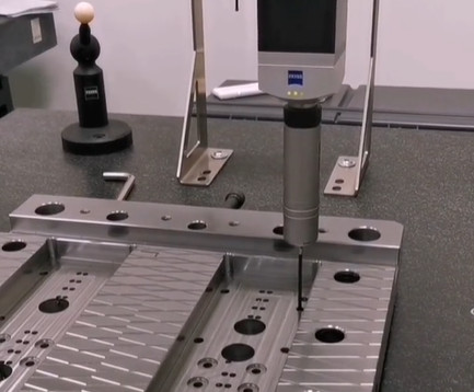
- Data Acquisition: A probe, either contact-based (touch-trigger or scanning) or non-contact (laser or optical), interacts with the object’s surface to collect coordinate points. These points form a point cloud representing the object’s 3D geometry.
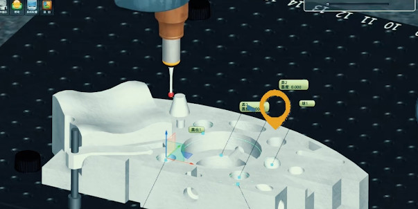
- Data Processing: Specialized software processes the collected data to create a digital model, which is compared to the nominal CAD model or engineering drawing to identify deviations in dimensions or tolerances.
- Reporting and Analysis: The software generates detailed reports, including measurements of GD&T parameters like flatness, cylindricity, or true position, often adhering to standards such as ASME B89.4.1 or ISO 10360.
The accuracy of CMM inspection depends on factors such as probe type, machine design, environmental conditions, and operator expertise. Modern CMMs can achieve volumetric accuracies as low as 1 µm, making them suitable for high-precision applications.
Components of a CMM
A CMM is a sophisticated system composed of several critical components, each contributing to its precision and functionality. The main components are outlined below:
| Component | 説明 | Key Specifications |
|---|---|---|
| Mechanical Structure | The frame, typically made of granite or steel, provides stability and rigidity. Common configurations include bridge, gantry, or cantilever designs. | Material: Granite (thermal stability); Measurement volume: 500 mm to 5 m. |
| Probe System | Contact probes (touch-trigger or scanning) or non-contact probes (laser, optical) collect coordinate data. | Accuracy: ±0.5 µm (contact); Resolution: 0.1 µm (laser). |
| Drive System | Motors and actuators move the probe along X, Y, and Z axes, often using air bearings for smooth motion. | Speed: Up to 800 mm/s; Repeatability: <1 µm. |
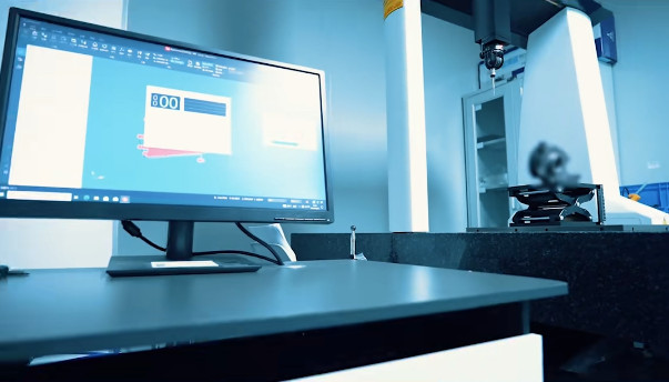
| 制御システム | A computer with specialized software controls the CMM, processes data, and generates reports. | Software: PC-DMIS, Metrolog, Calypso. |
| Measurement Table | A flat, stable surface (often granite) supports the workpiece during measurement. | Surface flatness: <2 µm; Load capacity: Up to 2000 kg. |
Types of CMMs
CMMs are available in various configurations, each suited to specific applications and workpiece sizes. The primary types include:
- Bridge CMMs: The most common type, featuring a bridge structure that moves the probe over a stationary workpiece. They are ideal for small to medium-sized parts and offer high accuracy (e.g., 1–3 µm). Suitable for automotive and aerospace components.
- Gantry CMMs: Designed for large, heavy workpieces, gantry CMMs have a moving table and a fixed or mobile gantry. They are used in industries like shipbuilding or wind energy, with measurement volumes up to 10 m.
- Cantilever CMMs: Featuring a single support arm, these are suitable for smaller parts with easy access. They are less common but useful for specific applications like toolmaking.
- Horizontal Arm CMMs: These have a horizontal probe arm, ideal for large, flat components like car bodies or sheet metal. They offer flexibility but may have slightly lower accuracy (e.g., 5–10 µm).
- Portable CMMs: Articulated arm CMMs or laser trackers are portable, allowing on-site measurements. They are less precise (e.g., 10–50 µm) but valuable for large assemblies or field inspections.
Each type is selected based on the workpiece size, required accuracy, and measurement environment, ensuring flexibility across applications.
Applications of CMM Inspection
CMM inspection is widely used across industries to ensure quality and precision. Key applications include:
- 品質管理: Verifying that manufactured parts meet design tolerances, such as dimensional accuracy (e.g., ±0.01 mm) or GD&T features like concentricity or perpendicularity.
- Reverse Engineering: Creating digital CAD models from physical objects by capturing their geometry, useful for replicating legacy parts without drawings.
- プロセスの最適化: Identifying manufacturing defects or variations to improve production processes, reducing waste and ensuring consistency.
- Tool and Die Inspection: Measuring molds, dies, and tooling to ensure they meet specifications before production begins.
- Assembly Verification: Checking the alignment and fit of assembled components, such as aircraft wings or automotive chassis, to ensure proper function.
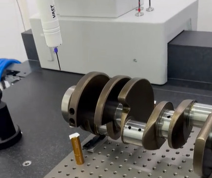
Industries like aerospace (e.g., turbine blade inspection), automotive (e.g., engine block measurement), and medical devices (e.g., implant verification) rely heavily on CMM inspection for their stringent quality requirements.
Technical Specifications of CMMs
CMM performance is defined by several technical specifications, which vary by model and application. The following table summarizes key parameters:
| 仕様 | Typical Range | 説明 |
|---|---|---|
| Measurement Accuracy | 1–10 µm | Volumetric accuracy, often specified as MPE (Maximum Permissible Error) per ISO 10360. |
| Measurement Volume | 500 mm to 10 m | The maximum size of the workpiece that can be measured, depending on CMM type. |
| Probe Resolution | 0.1–1 µm | The smallest detectable change in position, critical for high-precision measurements. |
| Scanning Speed | 100–800 mm/s | The rate at which the probe moves across the surface, affecting inspection time. |
| Temperature Range | 18–22°C | Optimal environmental conditions to minimize thermal expansion effects. |
Practical Considerations in CMM Inspection
While CMM inspection is highly effective, several practical considerations ensure optimal performance:
- 環境制御: Temperature variations can cause material expansion or contraction, affecting accuracy. A controlled environment (e.g., 20°C ±1°C) is critical, especially for high-precision measurements.
- Probe Selection: Choosing the right probe (contact vs. non-contact) depends on the material, surface finish, and required accuracy. For example, soft materials may require non-contact probes to avoid deformation.
- オペレーター・トレーニング: Skilled operators are essential for programming the CMM, interpreting results, and maintaining equipment. Improper setup or calibration can lead to measurement errors.
- Workpiece Fixturing: Secure and repeatable fixturing prevents movement during measurement, ensuring consistent results. Custom fixtures may be needed for complex parts.
- Software Compatibility: The CMM software must support the required GD&T standards and CAD formats. Regular updates ensure compatibility with modern design files.
These considerations, while not insurmountable, are critical to achieving reliable and repeatable measurement results. Addressing them systematically enhances the effectiveness of CMM inspection.
Kesu: Elevate Precision, Redefine Quality with CMM Inspection Excellence
Kesu delivers cutting-edge Coordinate Measuring Machine (CMM) inspection solutions, blending state-of-the-art technology with unmatched expertise to ensure your components meet the strictest design specifications. From aerospace turbine blades to medical device implants, our CMM systems—equipped with high-precision contact and non-contact probes, advanced data processing software, and tailored configurations, verifying GD&T compliance, dimensional precision, and geometric integrity with unwavering reliability. Kesu is among the top 5 best service providers of CNC precision machining parts in China.
結論
Coordinate Measuring Machine (CMM) inspection is a cornerstone of 精密製造, enabling accurate measurement of complex geometries and ensuring compliance with design specifications. By leveraging advanced probes, robust mechanical structures, and sophisticated software, CMMs provide unmatched precision for quality control, reverse engineering, and process optimization. Understanding the principles, components, types, applications, and technical specifications of CMM inspection equips manufacturers with the knowledge to implement this technology effectively. With proper environmental control, probe selection, and operator training, CMM inspection delivers reliable results, supporting industries that demand the highest standards of quality and precision.
Frequently Asked Questions (FAQs) About CMM Inspection
What is the main purpose of CMM inspection?
CMM inspection is used to precisely measure the 3D geometry of physical objects by capturing X, Y, and Z coordinates of their surfaces. Its primary goal is to verify that manufactured parts meet design specifications, including dimensional tolerances and geometric features (e.g., flatness, positional accuracy), ensuring compliance with CAD models or engineering drawings.
How accurate are CMMs?
CMMs offer high precision, with accuracies typically ranging from 1 to 5 micrometers (µm) for contact-based systems. Advanced models can achieve volumetric accuracies as low as 1 µm. Portable CMMs, such as articulated arms, are slightly less precise (10–50 µm) but provide flexibility for on-site measurements. Accuracy is maintained through calibration (per standards like ISO 10360) and controlled environments to minimize temperature or vibration interference.
Can CMMs measure complex geometries?
Yes. CMMs excel at measuring complex shapes, including freeform surfaces, intricate features (holes, slots, threads), and features defined by Geometric Dimensioning and Tolerancing (GD&T) standards. They can process point clouds of thousands of data points to recreate 3D models of even the most complex parts.
What environmental conditions are required for CMM inspection?
CMMs operate best in controlled environments to avoid external influences on precision:
温度: Typically 18–22°C (±1°C) to minimize thermal expansion/contraction of the machine or workpiece.
Vibration control: Isolation from vibrations (e.g., from nearby machinery) to prevent measurement errors.
Cleanliness: Dust-free conditions to protect probes and ensure accurate surface contact.
Can CMM inspection replace manual measuring tools?
CMMs complement rather than fully replace manual tools. While manual tools (calipers, micrometers) are suitable for simple, low-tolerance measurements, CMMs are necessary for complex geometries, high-precision tolerances (±0.001 mm), and automated, repeatable measurements of large or intricate parts.