This document provides a detailed guide on the CNC machining technology applied to titanium alloy "bird-shaped" support arm components. Through practical machining experience, a series of CNC machining process methods have been developed, including process planning, tool selection, cutting parameter settings, positioning methods, clamping techniques, and datum selection. These are critical technical conditions for successfully machining such components.
The increasing complexity of aerospace component structures demands advanced manufacturing techniques. The successful CNC machining of titanium alloy bird-shaped support arms represents a significant advancement in aerospace part production, providing valuable experience for similar components.
Material Properties of Titanium Alloy
Titanium alloy is a high-performance metal widely used in aerospace, aviation, and military applications due to its excellent strength-to-weight ratio, corrosion resistance, and thermal stability. However, it is a difficult-to-machine material, posing challenges such as low machining efficiency, high costs, and inconsistent quality.
The machining difficulties stem from the following material characteristics:
- Low chip deformation coefficient, leading to high cutting forces.
- Low thermal conductivity, causing elevated cutting temperatures.
- High chemical reactivity, resulting in severe tool wear and material sticking.
- High cutting force per unit area, increasing tool stress.
- Significant springback in machined surfaces, affecting dimensional accuracy.
These properties necessitate specialized machining strategies to achieve high-quality results while maintaining efficiency.
Component Description and Structural Analysis
Сайт titanium alloy bird-shaped support arm is a complex aerospace component with unique structural features that present significant machining challenges. This section details the component’s structure and analyzes its manufacturability.
Component Structure
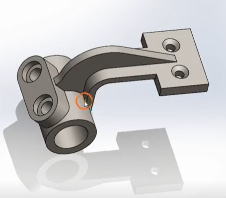
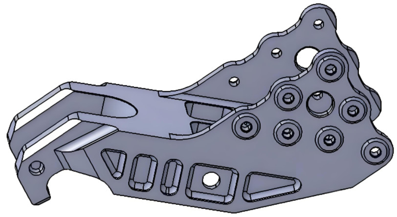
The bird-shaped support arm, made from TA15M titanium alloy forgings, has an outer dimension of 110 mm × 269 mm × 172 mm and a finished weight of 2.45 kg. The raw forging measures 310 mm × 180 mm × 120 mm and weighs approximately 31 kg. The component features a four-sided cavity structure with complex assembly relationships, requiring high dimensional accuracy and surface quality.
Key structural characteristics include:
- Four-sided cavity structure, complicating machining access.
- Irregular geometry, making clamping and positioning challenging.
- High, thin flanges (up to 95 mm) without support, prone to vibration.
- Thin webs and flanges (minimum thickness of 2 mm with ±0.2 mm tolerance).
- Multiple corner radii (R2 mm, R4 mm, R6 mm, R7 mm, and R10 mm).
Manufacturability Analysis
The structural complexity results in poor manufacturability. The primary machining difficulties are:
- Multiple Datum Transitions: The four-sided cavity structure requires at least four machining setups, with datum transitions introducing potential errors that can affect quality.
- Clamping and Positioning Challenges: The irregular shape complicates finding stable clamping points, hindering secure fixturing.
- High Flange Machining: The 95 mm high flanges, unsupported by stiffeners, are susceptible to vibration and tool deflection, making precision difficult.
- Varied Corner Radii: Multiple corner radii increase complexity in tool selection and CNC programming.
These challenges require careful process planning and tailored solutions to ensure successful machining.
Process Planning
Effective process planning is essential to address the machining challenges of the bird-shaped support arm. This section outlines the clamping and positioning strategy, machining process flow, and tool selection.
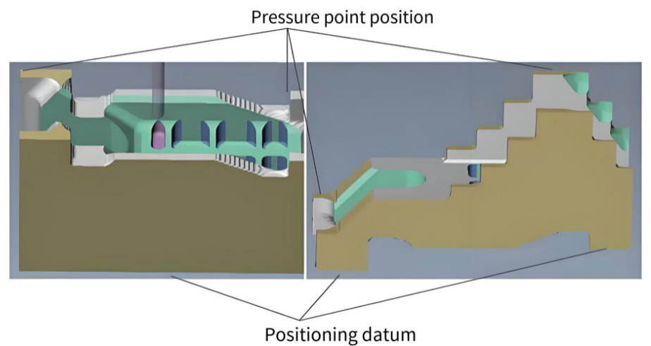
Clamping and Positioning Strategy
The irregular structure of the component makes stable clamping and positioning difficult. To address this, a process boss (craft lug) is introduced to provide a stable datum for machining. For the first and second faces, the positioning datum and clamping points are set on the process boss. For the third and fourth faces, the outer flange surfaces are used for positioning.
This approach ensures stability and accuracy during machining, accommodating the component’s irregular geometry.
Machining Process Flow
The machining process flow is designed based on the component’s structural features and manufacturing requirements:
- Receive forging material.
- Mill six-sided blank.
- Conduct ultrasonic and physicochemical inspection.
- Re-mill six-sided blank.
- Rough and finish machine the first face.
- Rough and finish machine the second face.
- Rough and finish machine the third face.
- Rough and finish machine the fourth face.
- Perform dimensional inspection.
- Conduct manual finishing (deburring).
- Perform semi-final inspection.
- Clean the component.
- Conduct fluorescent inspection.
- Perform sandblasting.
- Apply identification markings.
- Conduct final inspection.
- Package and deliver.
This process flow, combined with the clamping strategy, ensures all machining requirements are met while removing the process boss during setup transitions, achieving 100% CNC machining completion.
Выбор инструмента и параметры резки
Tool selection and cutting parameter settings directly influence deformation, efficiency, and precision. Given titanium alloy’s difficult-to-machine nature, carbide tools are preferred, including shallow-cut tools, solid carbide straight-shank tools, and indexable carbide tools.
With a material removal rate of 90%, rough machining prioritizes efficiency using shallow-cut tools with small depth of cut and high feed rates to control deformation. For finish machining, tools with diameters ≥30 mm use indexable carbide tools, while those <30 mm use solid carbide tools to ensure dimensional accuracy.
Cutting parameters are determined based on existing parameter libraries and practical machining conditions. Key parameters include spindle speed (n), depth of cut (ap), width of cut (ae), feed per tooth (fz), number of teeth (Z), and feed rate (vf), where vf = n × Z × fz. Most tools used are four-flute carbide tools, with spindle speed and feed per tooth being the primary factors affecting efficiency.
| Тип инструмента | Диаметр (мм) | Flutes | Spindle Speed (RPM) | Feed per Tooth (mm) | Глубина реза (мм) | Width of Cut (mm) | Feed Rate (mm/min) |
|---|---|---|---|---|---|---|---|
| Shallow-Cut (Roughing) | 50 | 4 | 1200 | 0.15 | 1.5 | 40 | 720 |
| Indexable Carbide (Finishing) | 30 | 4 | 1500 | 0.10 | 0.5 | 20 | 600 |
| Solid Carbide (Finishing) | 20 | 4 | 1800 | 0.08 | 0.3 | 15 | 576 |
CNC Programming
CNC programming is critical to achieving high-quality parts, influencing product quality, machining efficiency, tool life, and machine longevity. The programming process considers the component’s raw material state, structural features, machine capabilities, and tool characteristics.
Modern aerospace enterprises commonly use CATIA software for design and machining. CATIA’s modules, such as Machining, Part Design, Wireframe and Surface Design, and Sketcher, support programming, with the Machining module being the primary tool for CNC programming.
Programming Principles
The programming process follows these principles:
- Machine from high to low surfaces.
- Process outer features before inner ones.
- Perform rough machining before finishing.
Key programming considerations include optimizing tool paths to avoid complexity, selecting appropriate layering methods, avoiding vertical plunging, and reducing speed at corners. For shallow-cut programming, the “roughing” command in CATIA allows precise control of cutting range, depth, width, and tool lift height, ensuring uniform material allowance for subsequent machining.
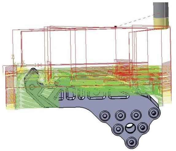
Моделирование и верификация
Program simulation is essential to prevent issues such as overcutting, residual material, or machine collisions. Using software to simulate post-processed programs allows verification of cutting results, reducing the risk of dimensional errors or part scrapping due to programming mistakes.
Заключение
CNC machining of titanium alloy bird-shaped support arm components is a complex process requiring meticulous planning and execution. The developed process scheme, including strategic clamping with process bosses, a structured machining flow, optimized tool selection, and precise CNC programming, provides a reliable framework for producing high-quality parts. This approach serves as a valuable reference for machining similar complex titanium alloy components in aerospace applications.