This guide provides a detailed overview of fault diagnosis and repair methods for common CNC machining equipment, including vertical drilling and tapping centers, CNC lathes, and CNC milling machines. The content focuses on mechanical and electrical faults frequently encountered in daily production. By systematically analyzing real-world cases, this article offers practical, experience-based solutions to assist CNC repair technicians in troubleshooting effectively.
Overview of CNC Machining Equipment
CNC machining equipment, such as vertical drilling and tapping centers, CNC lathes, CNC milling machines, and CNC punching machines, operates by executing programmed instructions to control machine components with high precision. A CNC system processes digital instructions based on part machining programs, issuing precise control commands to coordinate the movement of various components, resulting in accurately machined parts. These machines are known for their high accuracy, reliable system operation, and precise command execution. However, diagnosing and repairing faults in these systems can be complex due to their integrated mechanical and electrical components.
This article categorizes common faults in CNC equipment and provides step-by-step diagnostic and repair methods based on practical experience. The goal is to equip technicians with actionable insights for resolving similar issues efficiently.
Fault Diagnosis and Repair for Vertical Drilling and Tapping Centers
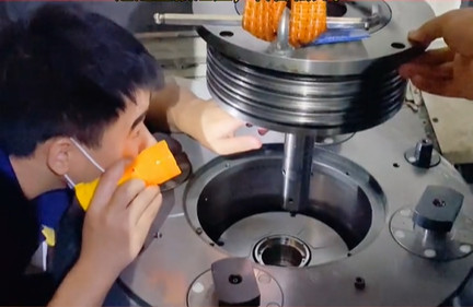
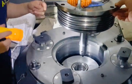
Vertical drilling and tapping centers are designed for tasks such as drilling, threading, and light milling. These machines typically consist of a spindle, an X-Y movable worktable (sometimes referred to as a cross-slide table), a tool magazine, and an A-axis. Tool magazine failures are among the most common issues encountered. Below is a detailed case study of a tool magazine fault in a TC500 vertical drilling and tapping center.
Fault Description
During operation, a TC500 vertical drilling and tapping center failed to execute tool change commands. In automatic mode, the tool magazine did not respond during a programmed tool change, and no alarms were displayed. Manual mode also failed to initiate a tool change.
Diagnosis and Analysis
Based on the operational principles of the vertical drilling and tapping center, the following potential causes were identified:
- Loss of tool position detection signal.
- Incorrect tool change signal.
- Loss of Z-axis coordinate reference point.
- Failure to detect the Z-axis position at the tool change point.
- Incorrect distance between the spindle lower surface and the worktable.
- Non-functional tool magazine motor.
Troubleshooting and Repair
The diagnostic process addressed each potential cause systematically:
- Tool position detection signal: The system’s ladder diagram was accessed (refer to system diagrams for TC500). A metal piece was used to test the tool position detection switch, confirming that the signal corresponded with the X9.6 contact in the ladder diagram, ruling out this cause.
- Tool change signal: In manual (MDI) mode, a tool change command was programmed, and the tool change relay and frequency converter output were verified as normal, eliminating this issue.
- Z-axis coordinate reference point: The Z-axis reference point was reset by moving the Z-axis to a mechanical coordinate of Z=130 using the handwheel, setting parameter 1815 APC(Z) to “0,” powering off, restarting, and setting APC(Z) to “1.” The tool magazine still did not function, ruling out this cause.
- Z-axis position at tool change point: The ladder diagram confirmed that the tool change point position signal was normal, excluding this issue.
- Spindle-worktable distance: The distance between the spindle’s lower surface and the worktable was adjusted to 540 mm, and system parameter K15’s bit “0” was set to “1.” The machine was powered off and restarted, but the issue persisted. Further adjustments to 535 mm, 530 mm, and 520 mm yielded no improvement, ruling out this cause.
- Tool magazine motor: The motor was disassembled and inspected, revealing that the power cable had broken at the terminal due to aging. After reconnecting the cable, the tool magazine operated normally during a test run.
Root Cause: The fault was caused by the tool magazine’s power cable being caught and severed by the rotating tool disc during operation. After repairing and securing the cable, the issue was resolved, and measures were implemented to prevent recurrence.
Fault Diagnosis and Repair for CNC Lathes
CNC lathes, typically equipped with X- and Z-axis worktables and a spindle, are used for turning and boring operations. Faults in these machines often involve the spindle’s electrical control system or the tool turret. The following case study details an electrical fault in an HTC2050i CNC lathe with a slanted guide rail.
Fault Description
During operation, the HTC2050i CNC lathe experienced a sudden fault, triggering the following alarms: NO.2121 (hydraulic motor power control switch tripped), NO.2123 (hydraulic motor failed to start), and NO.2130 (low chuck pressure). Inspection revealed that a single-phase 24V DC control circuit breaker in the electrical control cabinet had tripped. Forcing the breaker to close caused the CNC system to black out, with the DC power board’s indicator light flickering.
Diagnosis and Analysis
Based on the alarm messages and the machine’s operational principles, the following potential causes were considered:
- Faulty hydraulic station motor.
- Malfunctioning pressure relay for detecting hydraulic chuck pressure.
- Short circuit in the 24V DC power supply to the relay board.
Troubleshooting and Repair
The diagnostic process proceeded as follows:
- Hydraulic station motor: The motor was tested using a megger, confirming normal operation. Connecting the motor directly to the control power switch allowed it to start normally, ruling out this cause.
- Hydraulic chuck pressure relay: The pressure relay (SP3) was inspected, and its signal was found to be normal. Disconnecting the relay’s power line did not eliminate the alarms, excluding this issue.
- 24V DC power supply short circuit: The tripped breaker’s input and output lines were tested. The input was normal, but the +24V output was shorted to ground. The relay board’s connections were examined, revealing that all +24V lines were shorted to ground. Since all +24V lines were interconnected on the relay board, a single shorted line could affect the entire system. Testing identified the XT3 terminal (chip conveyor tension detection signal) as the source of the short circuit. Inspection showed that the signal line was caught by the chip conveyor’s tension wheel, severed during rotation, and shorted to the machine body. After repairing and securing the signal line, the fault was resolved, and the machine operated normally.
Root Cause: The fault resulted from a severed signal line causing a short circuit. Securing the line prevented future occurrences.
Fault Diagnosis and Repair for CNC Milling Machines
Фрезерование с ЧПУ machines, equipped with X- and Y-axis worktables and a spindle, are used for milling, grooving, and boring. Faults can be mechanical or electrical. The following case study addresses an electrical fault in a CK7136 CNC milling machine using a KND system, where the machine failed to return to its work zero point.
Fault Description
The CK7136 CNC milling machine failed to return to the zero point in the X, Y, and Z axes during startup, with the system displaying alarms for overtravel in all three directions (+X, +Y, +Z).
Diagnosis and Analysis
The following potential causes were identified:
- Faulty limit switches in each axis.
- Faulty limit switch wiring.
- Altered system parameters.
Troubleshooting and Repair
The diagnostic process included:
- Limit switches: Continuity tests confirmed that the X- and Y-axis limit switches functioned normally, but the Z-axis limit switch’s deceleration detection block failed to engage or disengage properly. Replacing the Z-axis limit switch resolved its issue. Diagnostic checks via the CNC system’s “Diagnosis” interface confirmed that only the Z-axis responded correctly to parameter changes (X000, X001, X002), but the machine still failed to return to zero, ruling out this cause as the sole issue.
- Limit switch wiring: Inspection revealed that the X- and Y-axis limit switch wiring had deteriorated due to prolonged exposure to oily coolant, causing insulation failure and short circuits with the machine body. After repairing the wiring, diagnostic tests confirmed normal operation, but the zero-point issue persisted, excluding this cause.
- System parameters: Accessing the “Parameter” interface revealed that parameter 0015 (zero-point settings for X, Y, Z) was incorrectly set to “01000001” instead of “01000111.” The parameter was corrected by enabling the parameter switch, entering “01000111” in the input field, and restarting the machine. After resetting alarms and rebooting, the machine returned to zero normally.
Root Cause: The fault was caused by a combination of a defective Z-axis limit switch and incorrect zero-point parameters, triggered by shorted wiring due to insulation degradation. Addressing both hardware and software issues resolved the problem.
Summary of Common CNC Faults and Repair Methods
The following table summarizes the faults discussed, their causes, and repair methods:
| Оборудование | Fault Description | Root Cause | Repair Method |
|---|---|---|---|
| Vertical Drilling and Tapping Center (TC500) | Tool magazine fails to execute tool change | Broken tool magazine motor power cable | Reconnect and secure power cable |
| CNC Lathe (HTC2050i) | Hydraulic motor and chuck pressure alarms, tripped breaker | Shorted chip conveyor signal line | Repair and secure signal line |
| CNC Milling Machine (CK7136) | Failure to return to zero point, overtravel alarms | Defective Z-axis limit switch and incorrect parameters | Replace limit switch, reset parameter 0015 to “01000111” |
Заключение
Обработка на станках с ЧПУ equipment integrates digital control, automation, and precision engineering, making fault diagnosis and repair a complex task. Effective troubleshooting requires a deep understanding of machine structure, operational principles, and both mechanical and electrical systems. Technicians must combine theoretical knowledge with practical experience to analyze faults systematically, identify root causes, and implement targeted repairs. By following a structured approach, as demonstrated in the case studies above, technicians can resolve faults efficiently and apply these methods to similar issues, ensuring reliable equipment performance.
FAQ: Common Faults and Repairs for CNC Machining Equipment
Why does a vertical drilling and tapping center fail to execute tool changes with no alarms?
Possible Causes: Common issues include loss of tool position detection signals, faulty tool magazine motors, incorrect Z-axis reference points, or broken power cables for the tool magazine.
Diagnostic Step: Check the tool magazine motor first (e.g., inspect for broken power cables due to aging or mechanical damage). If the motor is functional, verify Z-axis coordinates and tool change point signals using the system ladder diagram.
Example Fix: For a TC500 model, reconnecting and securing a severed tool magazine motor power cable (damaged by the rotating tool disc) resolved the issue.
What causes hydraulic motor and chuck pressure alarms on a CNC lathe?
Common Triggers: Tripped breakers, short circuits in 24V DC control circuits, faulty hydraulic motors, or damaged pressure relay signals.
Troubleshooting Tip: Start by checking the electrical control cabinet for tripped breakers. Test for short circuits in 24V lines (e.g., signal lines caught and severed by moving components like chip conveyors).
Case Example: On an HTC2050i lathe, a severed chip conveyor tension detection signal line shorted to the machine body, causing breaker trips. Repairing and securing the line resolved the alarms.
Why won’t a CNC milling machine return to its work zero point, showing overtravel alarms?
Likely Causes: Defective limit switches (e.g., Z-axis), damaged wiring (due to coolant or wear), or incorrect system parameters (e.g., zero-point settings).
Solution Steps:Test limit switches for continuity and proper engagement.
Inspect wiring for insulation damage (common with oily coolants).
Verify zero-point parameters (e.g., parameter 0015 on KND systems).
Example Fix: For a CK7136 milling machine, replacing a faulty Z-axis limit switch and correcting parameter 0015 to “01000111” restored zero-point functionality.
How do I systematically diagnose faults without error alarms?
Approach:Refer to the machine’s operational principles to list potential causes (e.g., mechanical vs. electrical).
Test each component step-by-step (e.g., motors, sensors, wiring) using tools like megohmmeters (for motors) or ladder diagrams (for signal checks).
Verify system parameters and reference points (e.g., Z-axis coordinates for tool changes).
Key Tip: Prioritize mechanical checks (e.g., broken cables, loose connections) before complex electrical or software issues.
What preventive measures reduce recurring faults?
Recommendations:Secure moving cables (e.g., tool magazine, chip conveyor lines) to prevent snagging or severing.
Regularly inspect wiring for insulation damage, especially in areas exposed to coolant or debris.
Periodically verify system parameters and reference points to avoid software-related errors.
Maintain tool magazines and limit switches to ensure proper signal detection.