
In batch CNC machining, maintaining dimensional accuracy is critical, especially when machining parts with cast blank surfaces as datum references. This article explores a practical case of machining a hydraulic valve body on a horizontal CNC machining center, addressing the challenge of achieving consistent dimensions for a thin-walled O-ring sealing groove concentric with a cast blank hole. The approach combines precise work coordinate system establishment, manual and automated measurement techniques, and systematic programming to ensure uniformity and eliminate defects such as wall breaches.
Part Structure and Machining Requirements
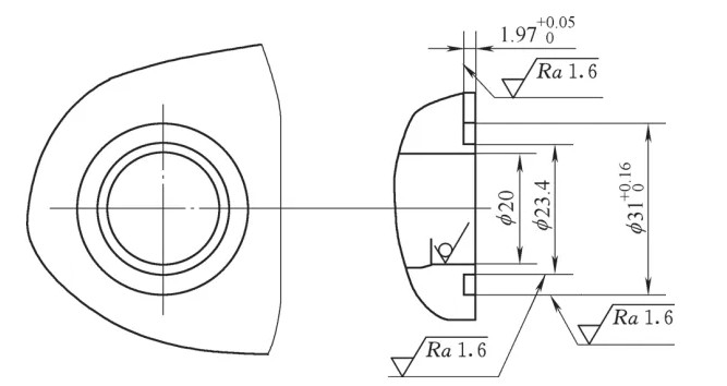
The hydraulic valve body discussed here requires machining an O-ring sealing groove concentric with a Ø20mm cast blank hole, as shown in Figure 1. The groove has a smaller diameter of 20mm, with a single-sided wall thickness of 1.7mm between the groove and the cast hole. The machining is performed on a horizontal CNC machining center using a forming tool. The cast blank hole, serving as the datum, has a positional casting tolerance of ±2mm, which introduces significant variability in part positioning. This variability, combined with the thin 1.7mm wall, makes it difficult to maintain dimensional consistency, often resulting in wall breaches or non-conforming parts.
The primary requirement is to ensure the O-ring groove is precisely aligned with the Ø20mm hole’s center, maintaining the 1.7mm wall thickness uniformly across all parts in the batch. The cast blank surface used for positioning introduces inconsistencies, as each part’s datum hole may be offset differently relative to the machine’s coordinate system.
Problem Analysis
The core issue in this machining process stems from using the cast blank surface as the positioning datum. The Ø20mm cast hole, which serves as the reference for the O-ring groove, has a positional tolerance of ±2mm due to casting variations. When parts are clamped, the actual position of the Ø20mm hole varies relative to the machine’s coordinate system. This variability directly affects the alignment of the forming tool, leading to inconsistent wall thicknesses. In severe cases, the thin 1.7mm wall is breached, resulting in scrap parts or defects that compromise the sealing function of the O-ring groove.
The machining process relies on the Ø20mm hole as the reference for concentricity, but the positional inconsistency of this hole across parts creates a significant obstacle. Without compensating for this variation, the CNC program cannot reliably position the tool to achieve the required 1.7mm wall thickness. The thin wall exacerbates the issue, as even minor misalignments can lead to dimensional deviations or structural failures.
Solution: Establishing a Dynamic Work Coordinate System
To address the positional variability of the cast blank hole, a dynamic work coordinate system (WCS) is established for each part before machining. This approach compensates for the inconsistent positioning of the Ø20mm hole by redefining the work origin based on the actual center of the hole for each part. Two methods are employed, depending on the machine’s capabilities: automated probe measurement and manual edge finder alignment. Both methods aim to locate the true center of the Ø20mm hole and update the WCS accordingly.
Automated Probe Measurement
For machines equipped with an automatic probe measurement system, a probe is used to locate the center of the Ø20mm cast hole. The process involves the following steps:
- The probe is activated to measure the position of the Ø20mm hole by contacting multiple points on its inner surface.
- An automatic centering program calculates the hole’s center coordinates relative to the machine’s coordinate system.
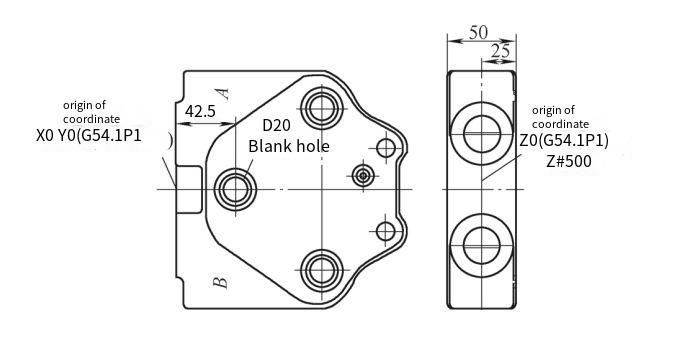
- The calculated center is used to offset the work origin to the hole’s actual center, as shown in Figure 2.
- The new work origin is written to the G54.1P1 coordinate system using the G10 instruction, ensuring the CNC program references the correct datum for machining the O-ring groove.
This method is highly efficient for batch production, as it automates the measurement and coordinate adjustment, reducing setup time and operator error. The probe’s precision ensures the work origin is consistently aligned with the hole’s center, enabling uniform wall thickness across parts.
Manual Edge Finder Alignment
For machines without probe systems, a manual edge finder is used in combination with variable programming to establish the WCS. The process is detailed as follows:
- Initial Positioning: The CNC program positions the spindle, equipped with an edge finder, near the approximate center of the Ø20mm hole (X42.5, Y0 in the G54.1P1 coordinate system). The Z-axis is set to a safe height (Z50) using tool length compensation (G43 H17).
- Manual Centering: The operator manually adjusts the X and Y axes using the edge finder to locate the true center of the Ø20mm hole. The edge finder contacts the hole’s inner surface at multiple points to determine the center accurately.
- Coordinate Capture: Once the edge finder is centered, the operator runs a program segment to capture the current X and Y mechanical coordinates, storing them in variables #501 and #502, respectively.
- Origin Calculation: The program calculates the work origin’s X-coordinate offset by adding 42.5mm to the absolute value of #501 and stores it in #503. The Y-coordinate (#502) and Z-coordinate (based on #500 + 25mm) are used to define the new origin.
- WCS Update: The G10 L20 P1 command writes the calculated X, Y, and Z coordinates to the G54.1P1 coordinate system, establishing the new work origin aligned with the hole’s center.
The programming sequence for manual alignment is provided in the table below for clarity.
| Program Block | Описание |
|---|---|
| N100 | Block identifier |
| #500 = -910. | Stores Z-axis mechanical coordinate of table rotation center to spindle face |
| M01 | Optional stop for operator verification |
| G90 G54.1 P1 G0 X42.5 Y0. | Rapid move to approximate Ø20mm hole position |
| G43 Z50. H17 | Apply tool length compensation, position Z at 50mm |
| M00 | Program stop for manual edge finder alignment |
| G0 G90 Z50. | Move Z to safe height after alignment |
| G31 | Initiate coordinate capture |
| #501 = #5021 | Store current X-coordinate in #501 |
| #502 = #5022 | Store current Y-coordinate in #502 |
| #503 = [ABS[#501]] + 42.5 | Calculate X-coordinate offset for work origin |
| G90 G10 L20 P1 X-#503 Y#502 Z[#500 + 25.] | Write new work origin to G54.1P1 |
| M01 | Optional stop for verification |
Implementation and Validation
Both the automated probe and manual edge finder methods were implemented in a production environment to machine multiple batches of hydraulic valve bodies. The key steps ensured that each part’s Ø20mm hole was accurately located before machining, allowing the O-ring groove to be cut with consistent 1.7mm wall thickness. The process was validated through the following measures:
- Проверка размеров: Post-machining measurements confirmed that the wall thickness remained within ±0.05mm of the target 1.7mm across all parts.
- Defect Elimination: No wall breaches or defective parts were observed in the batches processed using these methods.
- Повторяемость: The dynamic WCS establishment ensured consistent results across parts, regardless of the ±2mm casting tolerance.
The automated probe method proved faster and less prone to operator error, making it preferable for high-volume production. However, the manual edge finder method was equally effective for smaller batches or machines without probe capabilities, demonstrating the flexibility of the approach.
Practical Considerations
Several factors must be considered to ensure the success of this approach:
- Tooling Precision: The edge finder or probe must be calibrated regularly to maintain measurement accuracy.
- Operator Training: For manual alignment, operators need training to use the edge finder effectively and avoid errors during centering.
- Program Verification: The CNC program, especially the variable calculations and G10 commands, must be thoroughly tested to prevent coordinate errors.
- Machine Stability: The machining center must maintain positional accuracy during rapid movements and cutting operations to avoid introducing errors.
By addressing these considerations, the process can be scaled for different part geometries or machining centers, provided the core principle of dynamic WCS establishment is maintained.
Заключение
Ensuring dimensional accuracy in batch CNC machining of parts with cast blank datums requires a systematic approach to compensate for positional variability. By dynamically establishing a work coordinate system using either automated probe measurement or manual edge finder alignment, the machining process can achieve consistent results, even for thin-walled features like the 1.7mm O-ring groove discussed here. Validation through multiple production batches confirmed that these methods eliminated defects, maintained uniform wall thickness, and improved overall part quality. This approach is practical, repeatable, and adaptable to various CNC machining environments, providing a reliable solution for similar challenges in batch production.