The cycloid gear is a critical component of RV reducers, widely used in industrial robots, automated turntables, CNC machine tool turrets, and automated guided vehicles (AGVs). Its machining quality directly impacts the transmission accuracy and torsional rigidity of the RV reducer. Achieving high-efficiency machining of cycloid gears while maintaining stringent precision requirements is essential for large-scale production. This guide outlines a systematic approach to optimize cycloid gear machining through advanced fixture design, strategic tool selection, and optimized milling paths, resulting in a 30% reduction in processing time and consistent precision within ±0.01 mm.
Overview of Cycloid Gear Machining Requirements
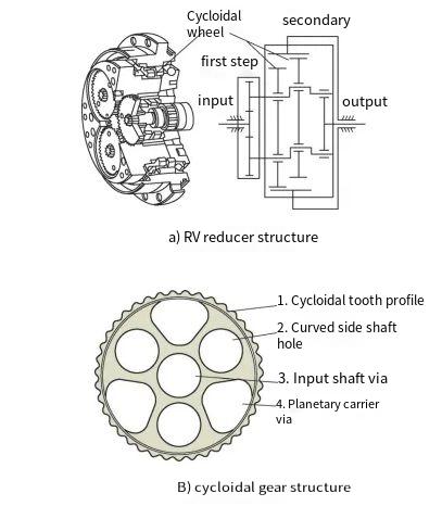
Сайт cycloid gear in an RV reducer features a complex cycloidal tooth profile and multiple internal holes, including crank shaft holes, input shaft holes, and planet carrier holes. These features demand high shape and positional accuracy, typically within 0.02 mm, to ensure the reducer’s performance. Traditional machining methods involve sequential processing: internal holes are machined first, followed by the cycloidal tooth profile using crank shaft holes as the positioning reference. This approach, however, introduces inefficiencies:
- Secondary clamping for tooth profile machining increases setup time.
- Small-diameter milling tools, necessitated by the tooth profile’s curvature, reduce material removal rates, extending processing time.
To address these limitations, an optimized machining strategy integrates single-clamping fixture design, multi-stage tool selection, and segmented milling paths to enhance efficiency and precision.
Fixture Design for Single-Clamping Machining
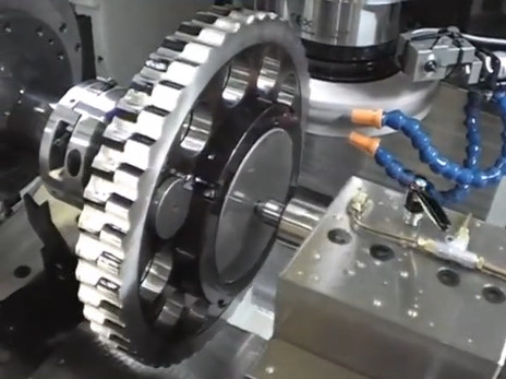
Efficient CNC machining begins with a robust fixture design that minimizes setup time and ensures positional accuracy. The proposed method uses the input shaft hole as the primary positioning reference, allowing simultaneous machining of the cycloidal tooth profile, crank shaft holes, and planet carrier holes in a single clamping operation.
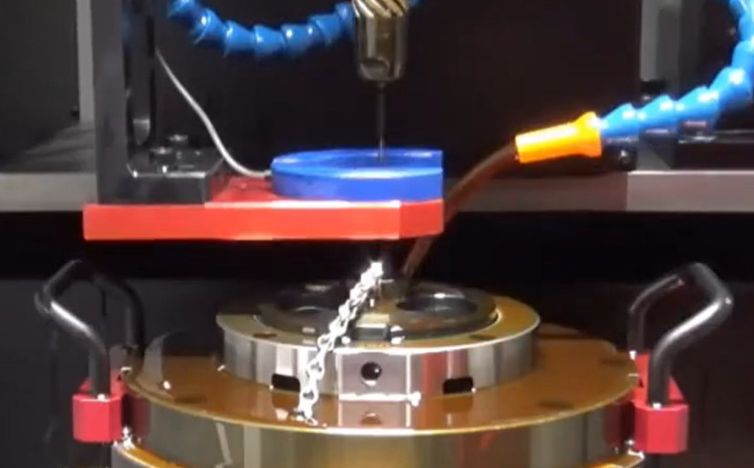
The fixture is secured to the CNC machine table, with the input shaft hole’s outer circle aligned as the machining zero point. The cycloid gear is clamped by compressing its upper and lower end faces, ensuring parallelism within 0.03 mm to prevent perpendicularity errors between the tooth profile, holes, and end faces. The fixture’s upper cover is designed to avoid interference with the internal holes, as shown in the clamping schematic.
Key considerations for the fixture include:
- Secure Fastening: The cycloid gear must be firmly clamped to prevent movement during machining, which could compromise positional accuracy between the tooth profile and crank shaft holes.
- Interference Avoidance: The fixture’s upper cover is shaped to clear the crank shaft, input shaft, and planet carrier holes, ensuring unobstructed tool access.
- Alignment Precision: The input shaft hole serves as the datum for all machining operations, eliminating errors from multiple setups.
By machining all features in one setup, this approach eliminates the time required for secondary clamping and reduces cumulative positioning errors, enhancing both efficiency and accuracy.
Tool Selection and Milling Path Optimization
The cycloidal tooth profile and internal holes require distinct machining strategies due to their geometric complexity. The internal holes are machined using layered milling, with special attention to the planet carrier hole’s transition fillet. The cycloidal tooth profile, defined by the following equation, presents unique challenges:
x = (rrp - D/2) * cos(θ) - e * cos(Z1 * θ)
y = (rrp - D/2) * sin(θ) - e * sin(Z1 * θ)
Где:
- rrp: Pitch circle radius of the needle gear (mm)
- D: Milling tool diameter (mm)
- e: Eccentricity (mm)
- Z1: Number of needle teeth
- Zc: Number of cycloid teeth
- θ: Angular parameter (radians)
To prevent overcutting or undercutting at the tooth root or crest, the milling tool diameter must satisfy D ≤ rrp. Typically, this restricts the tool diameter to 6 mm or less, reducing material removal rates and increasing machining time. To overcome this, a multi-stage milling strategy is employed, using three coated carbide tools with progressively smaller diameters (Tool 1#, 2#, and 3#).
Сайт milling process involves:
- Черновая фрезеровка: Tool 1# (largest diameter) removes bulk material, following an offset path derived from the cycloid equation to approximate the tooth profile.
- Semi-Finish Milling: Tool 2# (medium diameter) refines the profile, reducing the offset distance for greater accuracy.
- Финишная фрезеровка: Tool 3# (smallest diameter, ≤6 mm) completes the profile with high precision, ensuring surface roughness and shape accuracy.
Due to the cycloid gear’s thickness (>10 mm), layered milling is adopted, with each tool performing multiple passes at incremental depths. The final finish milling pass ensures the tooth profile’s geometric accuracy and surface quality. The milling paths are optimized to minimize tool travel and avoid interference, as illustrated in the milling path schematic.
This segmented approach increases material removal rates during roughing and maintains precision during finishing, reducing overall machining time by 30% compared to traditional single-tool methods.
Equipment and Accessory Specifications
The machining process demands high-precision CNC equipment to meet the cycloid gear’s stringent tolerances (geometric tolerances <0.02 mm). The selected CNC machine, tool holders, and cutting fluid must ensure stability, rigidity, and thermal management under high-speed conditions. The specifications are detailed in the table below:
| Component | Технические характеристики | Описание |
|---|---|---|
| CNC Machine | 5-axis CNC milling machine | Main spindle speed ≥12,000 RPM, positioning accuracy ≤0.005 mm |
| Tool Holder | HSK-A63 | Runout ≤0.003 mm, high rigidity for small-diameter tools |
| Cutting Fluid | Water-based synthetic coolant | High thermal conductivity, low viscosity, effective chip evacuation |
The 5-axis CNC machine provides the necessary flexibility for complex tool paths, while the HSK-A63 tool holder minimizes runout, ensuring consistent tool performance. The water-based coolant reduces thermal deformation and enhances chip removal, maintaining tool life and surface quality during high-speed milling.
Machining Process Implementation
The machining process follows a structured sequence to maximize efficiency and precision:
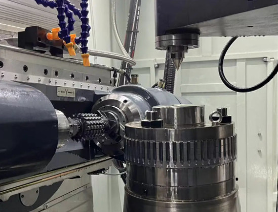
- Fixture Setup: Secure the fixture to the machine table, align the input shaft hole as the machining datum, and clamp the cycloid gear, ensuring end face parallelism <0.03 mm.
- Internal Hole Machining: Machine the crank shaft holes, input shaft hole, and planet carrier holes using layered milling. Apply a larger-diameter tool for roughing and a smaller tool for finishing the planet carrier hole’s transition fillet.
- Cycloidal Tooth Profile Machining: Execute the multi-stage milling strategy with Tools 1#, 2#, and 3#, following optimized paths derived from the cycloid equation. Perform layered milling for each tool, concluding with a finish pass to achieve surface roughness and shape accuracy.
- Quality Inspection: Use a coordinate measuring machine (CMM) to scan the tooth profile and holes, fitting the data to verify shape errors within ±0.01 mm and positional tolerances <0.015 mm.
This sequence ensures that all critical features are machined in a single setup, reducing setup time and maintaining positional accuracy. The CMM inspection confirms that the machined cycloid gear meets the required tolerances, as shown in the final part schematic.
Results and Performance Outcomes
The optimized machining strategy yields significant improvements:
- Processing Time Reduction: Single-clamping and multi-stage tool use reduce machining time by 30% compared to traditional methods.
- Precision Achievement: Tooth profile errors are controlled within ±0.01 mm, and positional tolerances between the tooth profile and crank shaft holes are <0.015 mm.
- Качество поверхности: The finish milling pass ensures surface roughness meets design requirements, enhancing the gear’s performance in RV reducers.
These outcomes demonstrate the effectiveness of the integrated approach, balancing efficiency and precision to support large-scale production of cycloid gears.
Заключение
High-efficiency cycloid gear machining for RV reducers is achievable through a systematic approach that integrates single-clamping fixture design, multi-stage tool selection, and optimized milling paths. By using the input shaft hole as the positioning datum, employing coated carbide tools with varying diameters, and leveraging high-precision CNC equipment, the proposed method reduces machining time by 30% while maintaining shape and positional accuracies within ±0.01 mm and 0.015 mm, respectively. This strategy provides a reliable and repeatable solution for producing high-quality cycloid gears, supporting the scalability of RV reducer manufacturing.