This document provides a comprehensive analysis of the machining process for split wheel tires, focusing on addressing technical challenges, designing a complete machining process, selecting specialized tools, and establishing inspection methods. The process was developed for the RQQ-1 turning center to achieve high-precision manufacturing, significantly improving product quality and machining efficiency. The methodology has been successfully applied in production for split wheel tires supplied to Iraq, enhancing the reputation of the manufacturing company in markets along the Belt and Road Initiative.
Technical Requirements of the Wheel Tire
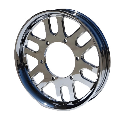
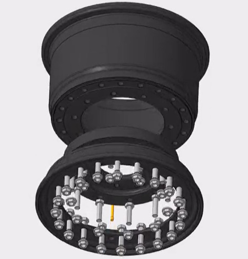
The wheel tire, a critical component of split wheels, is a profiled ring structure made from B2N material. Split wheels consist of a wheel tire, wheel core, and retaining ring, offering the advantage of replaceability and lower costs compared to integral wheels. However, the machining of each component is more complex. The wheel tire’s key technical specifications are as follows:
- Wheel core groove and retaining ring groove have an upward curvature with a 3:10 slope, requiring high dimensional accuracy.
- Inner wall dimensions: φ770.35 ± 0.05 mm, roundness ≤ 0.05 mm, concentricity with the outer circle ≤ 0.1 mm, and surface roughness Ra = 3.2 μm.
- Distance between wheel core groove and retaining ring groove: 86.25 ± 0.25 mm.
These stringent requirements, combined with the risk of deformation when clamping the outer circle for inner wall machining, pose significant challenges to achieving consistent precision.
Machining Challenges Analysis
The primary machining areas of the wheel machining are the inner wall, wheel core groove, and retaining ring groove. The key difficulties include:
- Ensuring dimensional and positional accuracy of the wheel core and retaining ring grooves due to their complex geometry and 3:10 slope.
- Maintaining inner wall roundness (≤ 0.05 mm) while minimizing deformation caused by clamping forces during machining.
- Developing effective inspection methods for the irregular shapes of the grooves, as conventional measuring tools are inadequate.
Previous attempts using general-purpose vertical lathes resulted in low machining efficiency and inconsistent precision, leading to frequent customer feedback on quality issues. To address these limitations, a specialized process was developed for the RQQ-1 numerical control turning center.
Process Route Design
To achieve high precision and efficiency, a three-stage machining process was established for the wheel tire, balancing rough, semi-finish, and finish machining. The process route is outlined below:
| Stage | Описание | Оборудование | Machining Details |
|---|---|---|---|
| Rough Machining | Process forged blank to remove excess material | General-purpose lathe | All contours (excluding grooves) machined with 3–4 mm allowance per side |
| Semi-Finish Machining | Refine contours to near-final dimensions | RQQ-1 Turning Center | Inner wall machined with 1.5 mm allowance per side; other areas to final dimensions |
| Finish Machining | Precision machining of critical features | RQQ-1 Turning Center | Inner wall, wheel core groove, and retaining ring groove machined to final specifications |
This structured approach ensures progressive refinement, reducing material stress and improving dimensional accuracy in critical areas.
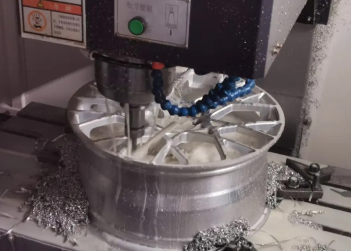
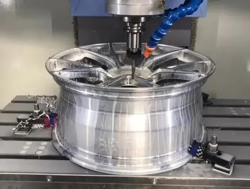
Finish Machining Process
The finish machining stage is the most critical, as it determines the final accuracy of the wheel tire’s inner wall and grooves. The process involves specialized tool selection, optimized clamping force, and precise machining steps.
Выбор инструмента
The complex geometry of the wheel core and retaining ring grooves, including small internal radii and a 3:10 slope, necessitates custom-designed tools. Standard diamond-shaped or round blades are unsuitable. After extensive consultation with tool manufacturers and testing, the following tools were selected:
- Custom Groove Tools: Designed for the wheel core groove (3 mm blade width) and retaining ring groove (4 mm blade width), tailored to the groove profiles.
- Conventional Tools: φ12 mm round blade for inner wall machining and 8 mm slotting blade for groove pre-machining.
These tools ensure precise cutting while minimizing tool wear and maintaining surface quality.
Clamping Force Optimization
Clamping the wheel tire’s flange during machining risks deformation, particularly affecting inner wall roundness. To mitigate this, clamping force was reduced from the standard 80 kG (used for integral wheels) to 20 kG. Repeated measurements confirmed that deformation at 20 kG was negligible, ensuring dimensional stability.
Finish Machining Steps
The finish machining process follows a systematic sequence to achieve the required precision:
- Setup and Alignment: Use the inner rim surface as the datum, clamp the flange, and align the tread using a dial indicator, controlling alignment error within 0.03 mm.
- Inner Wall Roughing: Machine the inner wall using a φ12 mm round blade, leaving a 0.3 mm allowance per side for final finishing.
- Groove Pre-Machining: Use an 8 mm slotting blade to remove excess material from the wheel core and retaining ring grooves, reducing the load on custom tools.
- Groove Finish Machining:
- Wheel Core Groove: Perform five-step turning with allowances of 1.5 mm, 1.1 mm, 0.7 mm, 0.3 mm, and 0 mm to prevent tool chipping and ensure accuracy.
- Retaining Ring Groove: Perform four-step turning with allowances of 1.3 mm, 0.8 mm, 0.3 mm, and 0 mm for similar reasons.
- Inner Wall Finishing: Complete final machining of the inner wall using a φ12 mm round blade to achieve φ770.35 ± 0.05 mm and Ra = 3.2 μm.
This multi-step approach ensures tool durability, minimizes vibration, and achieves the required precision.
Inspection Methods
Due to the irregular shapes of the wheel core and retaining ring grooves, conventional measuring tools are inadequate. Custom inspection templates were designed to verify dimensions and shapes accurately. The inspection process includes:
Inner Wall Measurement
The inner wall diameter (φ770.35 ± 0.05 mm) is measured using an inside micrometer for each piece, ensuring compliance with dimensional and roundness requirements.
Groove Shape Inspection
Custom templates for the wheel core groove and retaining ring groove are used to check shape accuracy. The gap between the template and groove must be ≤ 0.2 mm for acceptance.
Retaining Ring Groove Depth Inspection
A depth inspection template is placed radially in the retaining ring groove, using the inner wall as the datum. The template’s arc end must contact the groove bottom at the “pass” end while showing a gap at the “stop” end, and vice versa, to confirm a depth of 11 ± 0.5 mm.
Relative Position Inspection
A relative position template verifies the 86.25 ± 0.25 mm distance between the wheel core and retaining ring grooves. The template’s sloped ends must contact one groove’s slope while showing a gap at the other, and vice versa, to confirm positional accuracy.
Retaining Ring Groove Width Inspection
A width inspection template is placed in the retaining ring groove. The “pass” end must fit fully, while the “stop” end must not, confirming a width of 11.65 ± 0.35 mm.
| Inspection Item | Tool | Технические характеристики | Acceptance Criteria |
|---|---|---|---|
| Inner Wall Diameter | Inside Micrometer | φ770.35 ± 0.05 mm | Roundness ≤ 0.05 mm |
| Groove Shape | Shape Templates | Gap ≤ 0.2 mm | Conformance to profile |
| Retaining Ring Groove Depth | Depth Template | 11 ± 0.5 mm | Pass/stop criteria met |
| Groove Relative Position | Position Template | 86.25 ± 0.25 mm | Pass/stop criteria met |
| Retaining Ring Groove Width | Width Template | 11.65 ± 0.35 mm | Pass/stop criteria met |
Implementation Results
The developed process enabled efficient and precise machining of wheel tires on the RQQ-1 turning center. Key outcomes include:
- Achieved inner wall precision of φ770.35 ± 0.05 mm, roundness ≤ 0.05 mm, and surface roughness Ra = 3.2 μm.
- Ensured groove dimensional accuracy, with wheel core and retaining ring grooves meeting all specifications.
- Improved machining efficiency compared to general-purpose lathes, reducing production time and costs.
- Enhanced product quality, eliminating customer complaints and supporting market expansion in Belt and Road countries.
The process’s success demonstrates a reliable, systematic approach to high-precision machining of complex components.