Micro spherical head parts, characterized by small diameters and complex curved surfaces, pose significant machining challenges due to their size, structural fragility, and high precision requirements. Traditional machining methods often fail to meet the demands of these components, particularly for parts with diameters ≤3.5mm and hardness levels around 60HRC. This article outlines a specialized machining method using an optical curve grinding machine combined with custom-designed tooling to achieve high precision, high yield, and operational simplicity for micro spherical head parts.
Characteristics of Micro Spherical Head Parts
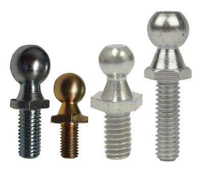
Micro spherical head parts are defined by their unique structural and material properties, which dictate the need for specialized machining approaches. These parts typically feature:
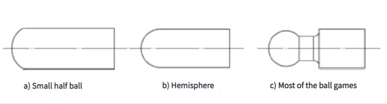
- Curved Spherical Head Structure: The parts have spherical surfaces at the shaft end, categorized as small hemispherical, hemispherical, or large hemispherical structures.
- Small Diameter: The spherical head diameter is generally ≤3.5mm, making precision machining difficult.
- High Hardness: Materials such as GCr15 with hardness ranging from 58–64HRC are common, requiring robust machining tools.
- Fragile Transition Segment: The transition segment between the spherical head and the shaft, often as small as 1.2mm in diameter, is prone to breaking under radial forces during machining.
- High Surface Quality Requirements: Surface roughness values of Ra=0.4μm are typically required, with no visible tool marks or defects.
- Tooling Sensitivity: The small size of the parts makes them highly sensitive to tool design and machining parameters.
These characteristics render traditional machining methods, such as CNC turning, cyclone milling, or forming grinding, inadequate for achieving the required precision and structural integrity, particularly for batch production.
Limitations of Traditional Machining Methods
Traditional machining methods for spherical head parts are designed for larger components (diameter ≥8mm) and are not well-suited for micro parts. The following methods are commonly used for larger spherical heads but face challenges with micro components:
- CNC Turning with Omnidirectional or Cycloidal Tools: Requires precise tool alignment and struggles with small diameters due to tool size limitations.
- Cyclone Milling: Demands high precision in tool positioning, which is difficult for micro parts with fragile transition segments.
- Forming Grinding with Specialized Wheels: Involves complex wheel dressing processes that are challenging for micro-scale applications.
- Generative Grinding with Custom Cup-Shaped Wheels: Effective for larger parts but impractical for micro parts due to wheel size and precision requirements.
- Filing with Specialized Grinding Blocks: Limited to simple hemispherical shapes and unsuitable for complex micro geometries.
For micro spherical head parts, these methods often result in low precision, frequent tool wear, and high risk of part breakage, particularly at the transition segment. For low-precision, small-batch production, soft-state milling followed by heat treatment and polishing may suffice, but this approach fails to meet the stringent requirements of high-precision components.

Optical Curve Grinding: A Specialized Approach
To address the limitations of traditional methods, a machining process using an optical curve grinding machine combined with custom tooling was developed. This approach leverages the principle of forming a spherical head through the envelope of a rotating arc, ensuring precision and structural integrity.
The optical curve grinding machine consists of a bed, coordinate worktable, grinding wheel table, and projection system. The worktable supports longitudinal, transverse, and vertical movements, while the grinding wheel performs rotational motion and linear movement along the guide rail. The wheel table also allows longitudinal and transverse feed motions and rotations around the X, Y, and Z axes. This setup enables the machining of complex surfaces, such as multi-arc surfaces, logarithmic curves, or Archimedean spirals.
The machine uses an optical projection system to magnify the workpiece (up to 25x or 50x) and project it onto a screen, where it is compared to a reference contour. The operator grinds away excess material until the workpiece contour aligns with the reference, ensuring high precision. Diamond grinding wheels, available in flat or pointed configurations, are used, with pointed wheels suitable for grinding curved surfaces as small as 0.2mm in diameter.
Custom Tooling Design
A specialized tooling setup was designed to complement the optical curve grinding machine. The tooling ensures stable workpiece rotation and precise alignment during machining. Key components include:
- Low-Power Motor: Operates at 1400 rpm to drive the workpiece rotation.
- Small Lathe Chuck: Fixed on the worktable, using a spring collet to securely clamp workpieces with diameters up to 10mm.
- Belt Drive System: Increases the chuck rotation speed to 2000 rpm, with the rotation direction opposite to the grinding wheel to optimize cutting efficiency.
- Height Adjustment Mechanism: Aligns the workpiece projection within the grinding wheel’s operational range.
The tooling ensures radial runout of ≤0.005mm, critical for maintaining precision during high-speed rotation. By fixing the grinding wheel height and eliminating its vertical reciprocating motion, the setup maximizes effective contact time between the wheel and the workpiece, improving machining efficiency.
Machining Process Design
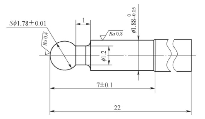
The machining process was designed to balance efficiency, precision, and tool longevity. A step-by-step approach using both flat and pointed grinding wheels was implemented to manage material removal and surface quality. The process for machining 500 micro spherical head parts (material: GCr15, hardness: 58–64HRC, surface roughness: Ra=0.4μm) is outlined below:
- Rough Machining with Flat Grinding Wheel:
- Segments A and B: Leave a machining allowance of 0.02mm.
- Segment C (spherical head): Leave a machining allowance of 0.1mm.
- Wheel translation speed: 3mm/min.
- Wheel rotation speed: 12,000 rpm.
- Contour Machining with Pointed Grinding Wheel:
- Segments A and B: Achieve final dimensional accuracy.
- Segment C: Leave a machining allowance of 0.01mm.
- Wheel translation speed: 1.5mm/min.
- Wheel rotation speed: 12,000 rpm.
- Finish Machining with Pointed Grinding Wheel:
- Segment C: Final grinding to achieve the required spherical contour and surface roughness.
- Wheel translation speed: 0.5mm/min.
- Wheel rotation speed: 12,000 rpm.
The flat grinding wheel, with its self-sharpening capability, is used for rough machining to remove large material volumes efficiently. The pointed grinding wheel, with a smaller corner radius, is reserved for contour and finish machining to minimize wear and ensure precision.
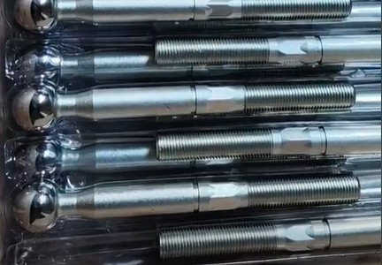
Machining Results and Validation
The proposed method was applied to produce 500 micro spherical head parts. The flat grinding wheel provided consistent cylindrical surface quality due to its self-sharpening feature, while the pointed wheel, used for finishing, required dressing only four times during the batch production, indicating low tool wear. The machining results were validated through dimensional and surface quality inspections, as summarized in the table below:
| Параметр | Requirement | Measured Value |
|---|---|---|
| Spherical Head Diameter | ≤3.5mm | 3.48 ± 0.02mm |
| Transition Segment Diameter | 1.2mm | 1.20 ± 0.01mm |
| Surface Roughness (Ra) | 0.4μm | 0.38–0.40μm</ gerekli> |
| Radial Runout | ≤0.005mm | 0.003–0.004mm |
| Defect-Free Surface | No tool marks | Compliant |
The results demonstrate that the method meets all design specifications, with high dimensional accuracy, excellent surface quality, and no visible defects. The low radial force during machining minimized the risk of breakage at the transition segment.
Advantages of the Proposed Method
The combination of optical curve grinding and custom tooling offers several advantages for machining micro spherical head parts:
- High Yield Rate: Consistent precision across large batches, with minimal defects.
- Operational Simplicity: The optical projection system simplifies contour alignment, reducing operator skill requirements.
- Precision Control: The process achieves tight tolerances (e.g., ±0.02mm for spherical head diameter) and excellent surface finish (Ra=0.4μm).
- Structural Integrity: Low radial forces protect the fragile transition segment, reducing breakage.
- Product Consistency: The method ensures uniformity across batch production, critical for high-volume manufacturing.
This approach effectively addresses the machining challenges of micro spherical head parts, offering a reliable and scalable solution for precision manufacturing.
Заключение
The machining of micro spherical head parts requires a departure from traditional methods due to their small size, high hardness, and fragile structures. The proposed method, utilizing an optical curve grinding machine with custom tooling, provides a robust solution for achieving high-precision machining. By leveraging a step-by-step process with flat and pointed grinding wheels, the method ensures dimensional accuracy, surface quality, and structural integrity. The validated results from a 500-part production run confirm the method’s effectiveness, making it a valuable approach for manufacturers dealing with micro spherical head components.