Cartridge valves are critical components in aerospace applications, requiring high-precision machining to meet stringent dimensional and surface quality standards. A common issue in machining cartridge valve holes is the formation of bellmouth defects, where the hole diameter widens at the entrance or exit, compromising precision and performance. This article provides a systematic approach to eliminating bellmouth defects through optimized machining parameters, refined processing methods, and customized forming tools, ensuring high precision and surface quality.
Cartridge Valve and Hole Structure
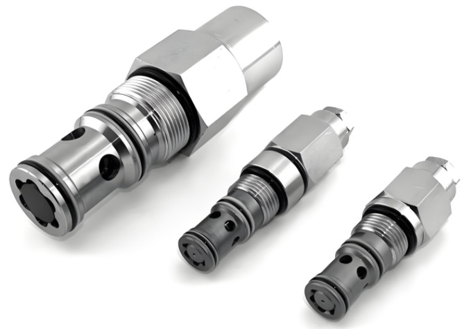
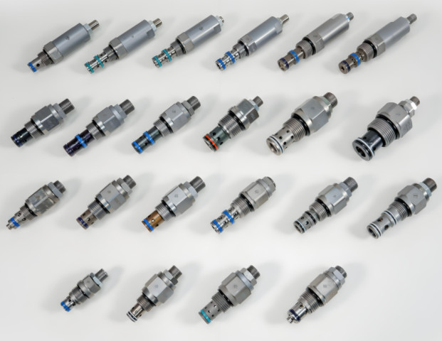
Cartridge valves, such as solenoid directional valves, check valves, relief valves, pressure-reducing valves, and flow control valves, are widely used in aerospace systems due to their compact design and reliability. Threaded cartridge valves simplify pipeline connections, reduce leakage risks, and allow easy replacement without disassembling pipe joints. The machining of these valves and their corresponding holes has been standardized to ensure consistency and performance.
Cartridge valve holes are typically multi-cavity structures, categorized as two-cavity, three-cavity, four-cavity, or five-cavity configurations. For instance, the Vickers C-10-3 three-cavity hole requires tight dimensional tolerances and surface roughness, with coaxiality tolerances generally within 0.02 mm. Transitions between cavities often feature small chamfers or fillets, demanding advanced machining techniques to achieve the required precision.
The semi-enclosed nature of multi-cavity holes poses challenges in chip evacuation, leading to chip accumulation and potential tool damage. Factors such as tool selection, equipment capabilities, and processing methods significantly affect machining accuracy and surface quality. Addressing these challenges requires a comprehensive strategy, including optimized tool selection, programming, and machining parameters.
Optimized Machining Methods
Traditional machining of cartridge valve holes involves multiple steps: center drilling, drilling, reaming, rough machining, semi-finish machining, finish machining, threading, and deburring. For aluminum valve blocks, this process often results in uneven material removal, particularly at cavity transitions, where chamfers or fillets complicate programming. Manual programming for these transitions is time-consuming and prone to errors, increasing the workload for operators.
In traditional methods, excess material at cavity transitions is not removed during rough machining, leading to high cutting forces during semi-finish machining, especially at the cavity bottom. Machine loads can increase to 40–50%, causing tool vibration or axial deviation, which contributes to bellmouth defects and dimensional inaccuracies. To address this, an optimized machining process uses automated programming software to streamline cavity hole machining.
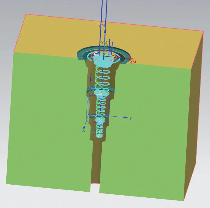
The optimized process involves forming the first counterbore during semi-finish machining, leaving a uniform 0.15 mm allowance on the cavity walls and bottom. This approach reduces cutting forces, improves chip evacuation, and minimizes tool vibration, effectively preventing bellmouth defects. The machining trajectory, as shown in typical process diagrams, ensures consistent material removal and enhances surface quality.
Tool Selection and Considerations
The choice of tools is critical for machining cartridge valve holes, particularly for materials like 7A04-T6 aluminum alloy, known for its high strength and good machinability. Solid carbide tools are preferred due to their high hardness, wear resistance, and chemical stability. These tools ensure consistent cutting performance and minimize surface defects. For optimal results, solid carbide end mills are recommended for one-pass forming, as they offer:
- Uniform cutting edges with excellent linearity, enabling high shape accuracy.
- High rigidity and strength, supporting precise machining and superior surface quality.
- Long cutting edges, allowing complete contour forming in a single pass, improving efficiency.
Tool specifications should match the cavity hole dimensions, with larger-diameter tools preferred for enhanced stability. Custom forming tools, typically made with a high-speed steel body and carbide cutting edges, are designed to match specific cavity profiles. To enhance tool durability, custom tools should incorporate 0.2–0.3 mm corner radii at cutting edges to prevent chipping under sudden load changes. Radial runout should be controlled within 0.01 mm, or machining trials should be conducted to verify tool accuracy.
Common tools include forming tools for cavity shaping, milling tools for general machining, and single-tooth thread milling cutters for threading, each tailored to specific machining requirements.
Cutting Method Selection
Traditional layer-by-layer machining methods have several limitations, including:
- Tool marks at layer transitions, affecting surface quality.
- Multiple tool entry and exit steps, increasing idle machine time and causing overcutting or undercutting due to variable cutting loads.
To overcome these issues, spiral milling is adopted for semi-finish machining. This method involves a continuous cutting feed, ensuring stable cutting forces and uniform material removal. Spiral milling minimizes tool deflection by gradually increasing the depth of cut, maintaining consistent hole dimensions from top to bottom. It also reduces idle machine time, as only one tool entry and exit is required per cavity, improving efficiency by approximately 30% compared to layer-by-layer methods.
Optimization of Cutting Parameters
Optimizing cutting parameters is essential for achieving uniform material removal and preventing bellmouth defects. In multi-cavity holes, cutting depths vary, and the maximum load occurs at the cavity bottom. To ensure stable machining, parameters must be adjusted based on the machining stage. During initial tool entry, cutting loads are 5–10% higher than during normal cutting. When machining sidewalls, cutting forces remain low due to minimal material removal. However, at 0.5 mm from the cavity bottom, cutting forces increase significantly.
To mitigate this, spindle speed should be reduced by 20–30%, and feed rates adjusted to maintain cutting loads within 10–15%. For larger cavities, slightly higher loads may be acceptable. A brief pause of 1–2 seconds at the cavity bottom enhances chamfer surface quality. For example, when machining a C-10-3 cavity hole, optimal parameters include a spindle speed of 300 rpm and a feed rate of 10 mm/min at the cavity bottom.
The optimized process eliminates the need for rough machining with forming tools, allowing direct finish machining with custom tools, further improving efficiency and precision.
Thread Machining Macro Program Optimization
Traditional threading programs lack flexibility and require frequent modifications, increasing programming complexity. An optimized macro program for single-tooth thread milling, designed for the Heidenhain system, enhances versatility and simplifies adjustments. The program defines key parameters such as thread depth (e.g., 15.88 mm), threads per inch (e.g., 14), and thread diameter (e.g., 25.4 × 0.875 / 2). It uses subroutines to control machining passes, with radial allowances adjusted incrementally (e.g., 0.3 mm and -0.185 mm).
The program ensures spiral milling with a maximum of 15 thread turns, limiting the total helix angle to 5,400 degrees to maintain stability. If additional turns are required, a separate helix segment is programmed. This approach streamlines threading, reduces programming errors, and ensures consistent thread quality.
Machining Results
The effectiveness of the optimized machining process is evident in the improved outcomes compared to traditional methods. The following table summarizes the results:
| Параметр | Before Optimization | After Optimization |
|---|---|---|
| Transition Fillet | Tool marks present | Smooth transition |
| Geometric Tolerances | Difficult to maintain | Fully achieved |
| Surface Quality | Poor (Ra > 0.8 μm) | Ra = 0.8 μm |
| Tool Life | Низкий | Significantly improved |
| Machining Efficiency | Низкий | 30% improvement |
These improvements result from the combined effect of optimized machining methods, tool selection, and parameter adjustments, ensuring high precision and surface quality while extending tool life.
Заключение
Eliminating bellmouth defects in cartridge valve hole machining requires a systematic approach, integrating optimized machining methods, advanced tool selection, and precise parameter control. By adopting spiral milling, custom forming tools, and automated programming, the machining process achieves uniform material removal, stable cutting forces, and superior surface quality. The optimized threading macro program further enhances efficiency and flexibility. These improvements have been validated through practical applications, offering a reliable framework for machining similar components in aerospace and other high-precision industries.