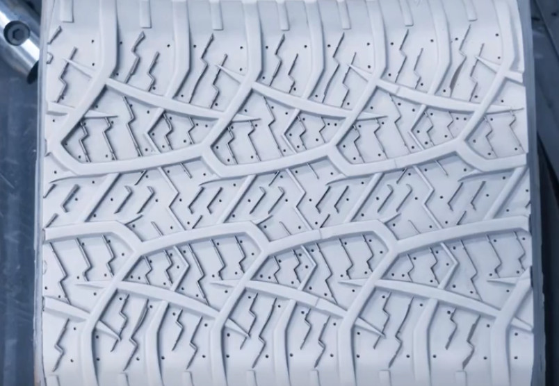
Tire molds are critical components in tire manufacturing, with the pattern blocks defining the tire’s tread shape and performance characteristics. The complexity of tire tread patterns poses significant challenges in CNC programming and machining. This guide details the application of hyperMILL software in five-axis CNC programming and machining for tire molds, emphasizing streamlined programming processes and optimized machining strategies to enhance efficiency and precision.
Overview of Tire Mold Manufacturing
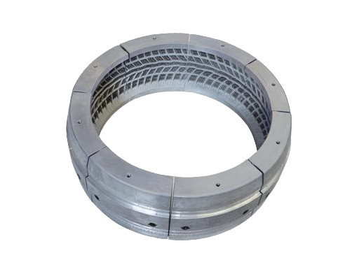
Tire molds, particularly for radial tires, consist of 8 to 12 pattern blocks that form the tire’s tread. These blocks are typically manufactured using either precision casting or direct machining. Direct machining, often performed with five-axis CNC systems, offers shorter production cycles, higher precision, and superior surface quality compared to casting. This method has become increasingly prevalent in modern mold manufacturing facilities due to its ability to handle intricate tread designs efficiently.
The manufacturing process begins with customer-provided data, including tire cross-sectional profiles, tread pattern layouts, and pitch arrangement sequences. These inputs are used to create 3D models, followed by material preparation, five-axis machining, and final manual finishing. The complexity arises from the varying pitch sizes—typically 3 to 5 basic pitches (P1, P2, P3, etc.)—arranged in specific sequences to form a complete tread pattern. Some patterns involve combined pitches, where features span multiple pitch segments, complicating programming and machining.
hyperMILL Programming Workflow for Tire Molds
hyperMILL, developed by OPEN MIND Technologies, is a modular CAD/CAM software optimized for 2.5D, 3D, and five-axis milling and turning. Its Tire module, combined with the Tireclock function, simplifies the programming of complex tire tread patterns by automating pitch replication and segment generation. The following sections outline the step-by-step workflow for programming tire mold machining pattern blocks using hyperMILL.
Step 1: Creating Pitch Arrangements with Tireclock
The process starts with importing customer-provided tread pattern data into a CAD system like UG (NX) to generate 3D models of individual pitches. These models, along with blank cross-sectional data, are imported into hyperMILL. The Tireclock module is used to define the pitch arrangement sequence and segment division angles. Users input pitch angles, arrangement sequences, and segment divisions into an Excel file, which Tireclock processes to generate a complete tire tread model and individual segment models. This automation eliminates manual replication of toolpaths, significantly reducing programming time.
For example, a tire mold with three pitch sizes (P1, P2, P3) and 10 segments (SEG_1 to SEG_10) can be configured by specifying the angular positions and sequence of pitches. The software automatically constructs the full tread model, ensuring accurate segmentation for subsequent programming.
Step 2: Single Pitch Programming
Programming begins with a single pitch, which serves as the foundation for generating toolpaths for all segments. Key aspects of single pitch programming include coordinate setup, tool selection, machining parameters, and strategy selection.
Coordinate Setup: The machining coordinate system is aligned with the workpiece coordinate system, centered on the tire’s rotational axis. This ensures that toolpaths for segment generation are created by rotating the single pitch toolpath around the axis, maintaining consistency across segments.
Tool Selection: Most tire mold machining pattern blocks are made from aluminum alloys, requiring tools with large chip evacuation spaces and sharp cutting edges to prevent chip adhesion. Common tools include:
- Round-nose end mills (e.g., D32mm R6mm) for machining flat surfaces like top and bottom faces.
- Flat-end mills (e.g., D12mm, D6mm, D3mm) for roughing and finishing tread grooves and arcs.
- Ball-end mills and tapered mills for finishing complex groove profiles.
Machining Parameters: Parameters are selected based on material properties, machine capabilities, and toolholder specifications. The table below summarizes typical parameters for key tools used in tire mold machining.
| Тип инструмента | Диаметр (мм) | Скорость резки (м/мин) | Feed Rate (mm/min) | Глубина реза (мм) |
|---|---|---|---|---|
| Round-nose end mill | 32 | 300–400 | 2000–3000 | 2–4 |
| Flat-end mill | 12 | 250–350 | 1500–2500 | 1-3 |
| Ball-end mill | 6 | 200–300 | 1000–2000 | 0.5–1 |
Machining Strategies: The machining process is divided into roughing and finishing stages.
- Blank Roughing: Pattern blocks are rotary components, and roughing can be done via turning or single-block milling. Single-block milling with 3D arbitrary stock roughing using a round-nose end mill removes excess material efficiently, minimizing setup changes.
- Groove Roughing: Groove roughing aims to shape the tread pattern. A D12mm flat-end mill is used for initial roughing, followed by D6mm and D3mm tools for secondary roughing to ensure uniform remaining stock. Cycloidal milling with an offset roughing strategy removes material from groove bases, leaving a 0.15mm allowance for finishing.
- Groove Base Finishing: The groove base, a curved surface with significant curvature, is finished using a D3mm flat-end mill with a five-axis linkage strategy. The base surface is selected as the drive surface, with adjacent grooves as stop surfaces to avoid collisions.
- Groove Top Finishing: For continuous circumferential grooves, 3D ISO surface machining with U/V line drives is used to minimize machining time. For non-continuous grooves, 3D projection finishing is applied.
- Groove Sidewall Finishing: Five-axis side-edge machining is used, with the sidewall as the drive surface and the groove base as the bottom surface. The tool axis is automatically adjusted to align the side edge with the sidewall, ensuring a single-pass finishing program.
Step 3: Segment Toolpath Generation
After programming a single pitch, hyperMILL uses the Tireclock data to generate toolpaths for all segments. For independent grooves within a single pitch, the single pitch program suffices. For combined pitches, the software identifies all possible pitch combinations and programs them similarly to single pitches. Features like grooves are defined as macros, allowing the software to apply the programmed toolpath to all relevant pitches automatically. The user selects the desired segment number, and hyperMILL generates the corresponding toolpaths, trimming paths that extend beyond segment boundaries. For symmetrical tread patterns, toolpaths can be mirrored 180° to cover both sides, further reducing programming effort.
Step 4: Collision Simulation and Verification
Before machining, toolpaths are verified for collisions involving the workpiece, machine, tool, toolholder, and fixtures. hyperMILL offers three simulation methods: internal simulation, internal machine simulation, and hyperVIEW. The table below compares their capabilities.
| Simulation Method | Workpiece Collision | Machine Collision | Toolpath Visualization |
|---|---|---|---|
| Internal Simulation | Yes | No | Basic |
| Internal Machine Simulation | Yes | Yes | Умеренный |
| hyperVIEW | Yes | Yes | Advanced |
In this process, hyperVIEW is used for comprehensive collision checks, incorporating pre-set blank dimensions, machine models, tools, toolholders, and fixtures. If no collisions are detected, the software generates NC code and a program list. The NC code is uploaded to the CNC machine, and the operator configures tools according to the program list. A typical setup involves a DMG MORI HSC75 linear machine with a Heidenhain 530 system, using HSK-A63 toolholders and a maximum spindle speed of 18,000 rpm.
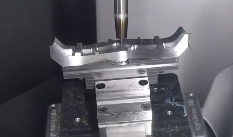
Machining Outcome
The final machined pattern block achieves high precision and surface quality, as shown in the completed product. The use of hyperMILL’s Tire module and five-axis strategies ensures efficient toolpath generation, minimizing redundant movements and optimizing tool performance. This results in reduced machining times and improved product quality, meeting the demands of complex tire tread designs.
Заключение
The application of hyperMILL in tire mold five-axis CNC programming and machining streamlines the handling of complex tread patterns. By leveraging the Tireclock module and optimized five-axis strategies, the software simplifies programming, reduces machining time, and enhances precision. This approach maximizes the capabilities of five-axis CNC machines, enabling manufacturers to produce high-quality tire molds efficiently and maintain competitiveness in demanding markets.