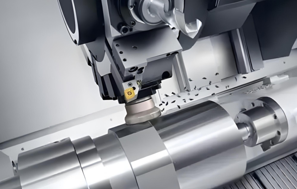
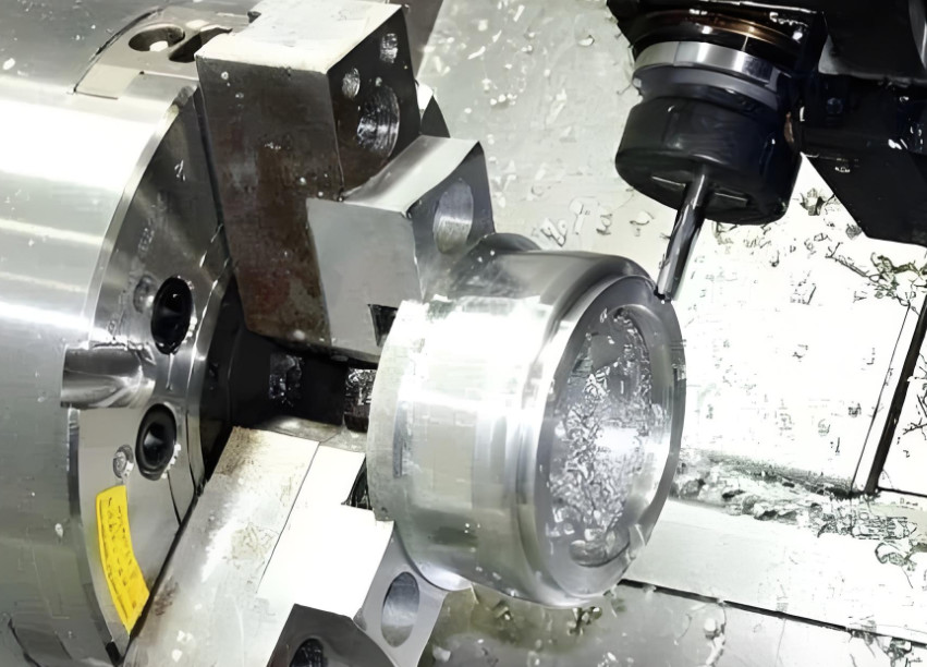
Turning machining is a fundamental metal cutting process performed on a lathe, utilizing the workpiece's rotational motion and the tool's linear or curved motion to shape and size the blank according to design specifications. The cutting energy in turning is primarily provided by the workpiece rather than the tool, making it one of the most common and essential machining methods in manufacturing.
Turning is ideal for machining rotational surfaces, such as internal and external cylindrical surfaces, conical surfaces, end faces, grooves, threads, and formed surfaces. The primary tool used is the turning tool. Lathes, which account for approximately 50% of metal-cutting machine tools, are versatile, allowing operations like drilling, reaming, threading, and knurling using tools such as drills, reamers, taps, and knurling tools.
Lathes come in various types, including horizontal lathes, floor lathes, vertical lathes, turret lathes, and profiling lathes, with horizontal lathes being the most common.
Key Steps in Turning Machining
While CNC turning may seem straightforward, it requires careful attention to detail. Below are the critical steps for successful turning operations.
Preparation Before Machining
- Verify Documentation and Materials: Ensure all drawings and specifications are complete and check if the blank meets requirements.
- Understand Requirements: Thoroughly review all documentation, mastering the use of fixtures and operational methods.
- Inspect Equipment: Check the lathe, prepare necessary accessories, lubricate the machine as per guidelines, and conduct a trial run.
Clamping and Machining
- Clean Tools: Wipe tool holders, shanks, and guide sleeves clean before clamping.
- Clean Workpiece and Fixture: Ensure positioning and clamping surfaces, as well as fixtures, are free of burrs and debris.
- Tool Overhang: The turning tool shank should not extend beyond four times its diameter or width.
- Tool Alignment: The tool shank centerline should be perpendicular or parallel to the feed direction.
- Workpiece Clamping: For three-jaw chucks, ensure the workpiece diameter is less than 30mm with an overhang not exceeding five times the diameter; for diameters over 30mm, use a center or follow rest if needed.
- Irregular Workpieces: Use counterweights for irregular or off-center workpieces clamped with four-jaw chucks or faceplates.
- Step Machining: Machine larger diameters first to ensure rigidity, followed by smaller diameters. Cut grooves before finish turning to prevent deformation.
- Drilling Preparation: Flatten the workpiece end face before drilling and create a center hole if necessary.
- Single Clamping: Complete turning in one clamping for surfaces with positional tolerances.
- Grinding Allowance: Leave 0.2-0.4mm for external surfaces and 0.15-0.3mm for internal holes, depending on workpiece length and deformation risks.
- First-Piece Inspection: In batch production, inspect the first piece before proceeding.
Post-Machining Handling
- Clean Workpiece: Ensure the workpiece is free of chips, water, or dirt and placed in a designated location to avoid damage.
- Clean Tools and Fixtures: Wipe tools and fixtures clean and store them properly.
- Maintain Documentation: Keep drawings and documents organized and clean.
Turning Parameters and Allowances
Grinding Allowances:
- External Surfaces: Leave a single-side allowance of 0.2-0.4mm, using smaller values for non-heat-treated materials like Cr12 or Cr12MoV and larger values for heat-treated parts.
- Internal Surfaces: Leave a single-side allowance of 0.15-0.3mm, following the same material considerations.
Cutting Parameters:
- External and End Face Turning: Adjust cutting speed, feed rate, and depth of cut based on material and tool type.
- Grooving and Cutting Off: Use lower feed rates to prevent tool damage.
- Бурение: Maintain cutting speeds of 18-25m/min, reducing speed for tool steel.
Self-Inspection During Machining
- Review Requirements: Understand drawing and process requirements, including machining areas and tolerances.
- Verify Blank: Ensure the blank and previous processes meet specifications.
- Continuous Inspection: Regularly check for tool interference, proper datum selection, and secure clamping. Verify dimensions, positional tolerances, surface roughness, and fit requirements.
- Adjust Parameters: Correct cutting parameters based on inspection results.
- Final Inspection: Confirm compliance with drawings before removing the workpiece, then send it for professional inspection.
Safety Considerations in Turning Machining
Turning is widely used in manufacturing, but its extensive use of tools and fixtures makes safety critical. Key safety concerns include:
Chip Hazards and Protection
Steel workpieces produce tough, sharp, plastically curled chips during turning. High-speed cutting can generate hot, long chips that may entangle the workpiece, tool, or tool holder, posing injury risks. To mitigate:
- Use hooks to clear or break chips promptly, stopping the machine if necessary. Never remove chips by hand.
- Implement chip-breaking measures, such as grinding chip-breaking grooves or steps on the tool, using chip breakers, or securing tools mechanically.
- Add protective shields to control chip flow and prevent injury.
Workpiece Clamping Safety
Improper clamping can damage the machine, break tools, or cause workpieces to fall or fly out. To ensure safety:
- Use appropriate fixtures for different workpiece sizes and shapes, ensuring secure and reliable connections to the spindle.
- Align and clamp workpieces firmly, using centers or support frames for large workpieces to prevent shifting or ejection.
- Remove wrenches immediately after clamping.
Operational Safety
- Inspect the lathe thoroughly before operation and ensure proper tool and workpiece clamping.
- Stop the machine when changing tools, loading/unloading workpieces, or measuring.
- Avoid touching rotating workpieces or wiping them with cotton cloth.
- Select appropriate cutting speeds, feeds, and depths to avoid overloading.
- Keep the machine clear of workpieces, fixtures, or debris.
- Use files safely by positioning the tool away from the workpiece and keeping the right hand forward to prevent entanglement.
- Assign dedicated personnel for machine operation and maintenance.
Error Compensation in Turning Machining
Modern manufacturing demands high precision, making error compensation a critical technique for improving machining accuracy. Thermal and geometric errors are the primary contributors to machining inaccuracies.
Definition and Characteristics
Error compensation involves creating a controlled error to offset or reduce the original error. By analyzing error patterns, a mathematical model is developed to generate an equal and opposite error, minimizing machining inaccuracies and enhancing dimensional precision.
Characteristics:
- Scientific: Error compensation integrates advanced technologies like sensing, signal processing, and computer control, forming a key branch of precision engineering.
- Engineering: It achieves high precision at lower costs compared to traditional methods, solving challenges that are otherwise difficult or expensive to address.
Sources of Thermal Errors
Thermal errors arise from heat sources such as motors, bearings, hydraulic systems, ambient temperature, and coolant, causing deformation in machine components. Geometric errors stem from manufacturing defects, assembly inaccuracies, and dynamic or static displacements.
Compensation Methods
Two main approaches to improve accuracy are:
- Error Prevention: Eliminates error sources through design and manufacturing improvements, though it is costly and cannot fully eliminate thermal deformation.
- Error Compensation: Uses software or hardware to correct errors. Software compensation, leveraging computer control, is more flexible and cost-effective than hardware compensation, which relies on fixed mechanical adjustments.
Developing high-precision, low-cost thermal error compensation systems is essential for correcting thermal drift between the spindle and tool, improving accuracy, reducing defects, and enhancing efficiency.
Common Issues in Turning Machining
Common problems in turning, such as bed saddle vibration during heavy thread cutting or tool plunging during cut-off operations, can lead to surface imperfections or tool breakage. These issues often arise due to:
- Axial Gaps: Gaps in the lead screw or nut cause the saddle or tool to move erratically, especially during heavy cutting with the right cutting edge.
- Force Dynamics: Axial forces in thread cutting or radial forces in cut-off operations exacerbate instability if gaps exist.
Решения
- Adjust the saddle and guide rail clearance to increase friction and reduce movement, ensuring smooth operation.
- Minimize slide plate clearance and secure the tool to prevent shifting.
- Reduce workpiece and tool overhang, use the left cutting edge when possible, and sharpen tools to minimize axial forces.
- Increase the rake angle of the right cutting edge to reduce cutting forces.
General Guidelines for Turning Machining
Adhering to standardized practices ensures consistent quality and safety. Key guidelines include:
Tool Clamping
- Limit tool shank overhang to 1.5 times its height (except for grooving or boring).
- Align the tool shank perpendicular or parallel to the feed direction.
- Adjust tool tip height: equal to the workpiece axis for end faces, threads, or cut-offs; slightly higher for rough turning or boring; slightly lower for slender shafts or hollow workpieces.
- Ensure thread tool alignment and secure clamping with minimal, flat shims.
Workpiece Clamping
- Limit overhang to five times the diameter for workpieces under 30mm and three times for larger diameters.
- Use counterweights for irregular workpieces and align tailstock centers for shaft machining.
- Use follow rests or center frames for slender shafts, ensuring proper lubrication and minimal tailstock sleeve extension.
- Secure high or narrow workpieces on vertical lathes with extended jaws or tie rods.
- Align castings or forgings to ensure uniform wall thickness.
Machining Practices
- Machine larger diameters first, followed by smaller ones, and cut grooves before finish turning.
- Flatten end faces before drilling and use pilot holes for deep drilling.
- Use tool shanks 0.6-0.7 times the hole diameter for small holes (10-20mm) and clamped tool heads for larger holes.
- Test-cut multi-start threads or worms after adjusting gears.
- Monitor tool wear and surface quality during automatic lathe operations.
- Avoid moving the crossbeam on vertical lathes after tool setup.
- Complete positional tolerance surfaces in one clamping and mark gear blanks near the pitch circle if needed.
Заключение
Turning machining is a cornerstone of modern manufacturing, offering versatility and precision for a wide range of applications. By following proper preparation, clamping, machining, and safety protocols, operators can achieve high-quality results while minimizing errors and risks. Error compensation techniques, particularly for thermal and geometric errors, play a crucial role in enhancing precision and efficiency, making them vital for meeting the demands of high-accuracy production.
Часто задаваемые вопросы (FAQ)
Generation and Causes of Tool Biting and Breaking Problems
When turning threads with a small pitch, the straight feed cutting method is generally adopted (feeding linearly in the direction perpendicular to the workpiece axis); when turning threads with a large pitch, in order to reduce the cutting force, the left-right borrowing feed cutting method is often used (by moving the compound rest to make the thread turning tool cut with the left and right cutting edges respectively).
When turning threads, the movement of the carriage is realized by the rotation of the long lead screw driving the movement of the split nut. There is an axial clearance at the bearing of the long lead screw, and there is also an axial clearance between the long lead screw and the split nut.
When using the left-right borrowing feed cutting method to strongly turn a right-hand worm and cutting with the right main cutting edge, the tool bears the force P exerted by the workpiece (ignoring the friction between the chip and the rake face). Decompose the force P into an axial component force Px and a radial component force. The axial component force Px is in the same direction as the feed direction of the tool. The tool transmits this axial component force Px to the carriage, thereby pushing the carriage to rapidly and violently move back and forth towards the side with the clearance. As a result, the tool moves back and forth, and ripples are generated on the machined surface, and even the tool breaks.
However, this phenomenon does not occur when cutting with the left main cutting edge. When cutting with the left main cutting edge, the axial component force Px borne by the tool is opposite to the feed direction and moves in the direction of eliminating the clearance. At this time, the carriage moves at a uniform speed.
When cutting off, the movement of the cross slide is realized by the rotation of the cross slide lead screw driving the movement of the nut. There is an axial clearance at the lead screw bearing, and there is also an axial clearance between the lead screw and the nut.
When cutting off on a lathe, the rake face of the tool (with a rake angle) bears the force P exerted by the workpiece (ignoring the friction between the chip and the rake face). Decompose the force P into a force Pz and a radial component force. The radial component force is in the same direction as the feed direction of the cut-off turning tool, pointing to the workpiece and pushing the tool into the workpiece, thus pulling the cross slide to move towards the direction with the clearance, causing the cut-off tool to suddenly bite into the workpiece, resulting in tool biting (breaking) or workpiece bending.
Solutions for Tool Biting and Breaking
When turning threads with a large pitch using the left-right borrowing feed cutting method, in addition to adjusting the relevant parameters of the lathe, the fit clearance between the carriage and the lathe bed guide rail should also be adjusted to be a little tighter, so as to increase the friction force during movement and reduce the possibility of carriage movement. However, this clearance should not be adjusted too tightly, and it should be appropriate to be able to shake the carriage smoothly.
Adjust the clearance of the cross slide well to make the clearance as small as possible; adjust the tightness of the compound rest to be a little tighter to prevent the turning tool from shifting during turning. The extension lengths of the workpiece and the tool shank should be shortened as much as possible, and the left main cutting edge should be used for cutting as much as possible; when cutting with the right main cutting edge, the depth of cut should be reduced;
Increase the rake angle of the right main cutting edge, and the cutting edge should be straight and sharp, so as to reduce the axial component force Px borne by the tool. Theoretically, the larger the rake angle of the right main cutting edge, the better.