The machining of deep rectangular spiral grooves on large-scale sleeve components, such as the inner liner of a 41MN carbon extruder, presents significant technical challenges due to the large pitch, deep groove profile, and stringent surface quality requirements. This article details a systematic approach to improving the machining process for a ZG35CrMo inner liner with a 200mm pitch, 50mm × 25mm × R16mm double-headed deep rectangular spiral groove. The optimized process enhances efficiency, ensures high surface quality, and achieves precise dimensional accuracy through refined tool selection, cutting strategies, and CNC programming.
Component Specifications and Machining Requirements
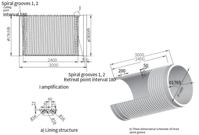
The inner liner, a critical component of a 41MN carbon extruder, is made of ZG35CrMo with a heat-treated hardness of 200–260 HBW. The component has an outer diameter with a wall thickness of less than 90mm and a length of 2,400mm. It features a double-headed deep rectangular spiral groove with a 200mm pitch, a cross-sectional dimension of 50mm × 25mm, and a root radius of 16mm. These grooves facilitate kerosene circulation for heating within the extruder’s material chamber. The large pitch, deep profile, and substantial material removal make traditional machining methods inefficient and prone to poor surface quality.
Initial Machining Challenges
Early attempts to machine the spiral grooves utilized a single 8mm-wide turning tool for profiling, requiring a low feed rate due to the significant cutting resistance. This approach resulted in a machining time of 120 hours per component, with poor surface quality that failed to meet production standards. Subsequent trials with a single forming tool simplified programming but introduced issues such as excessive tool-workpiece contact, leading to vibrations, tool chipping, and restricted cutting parameters. These limitations necessitated a multi-tool, multi-stage machining strategy to overcome the constraints of large material removal and ensure precision.
Optimized Machining Process
The optimized process addresses the inefficiencies of initial methods by incorporating a multi-tool approach, precise tool alignment, and strategic cutting methods. The process is divided into setup, tool selection, cutting strategy, and CNC programming, ensuring high efficiency and surface quality.
Workpiece Setup and Process Sequencing
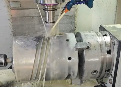
To enhance system rigidity and minimize vibration, the inner liner is clamped using a chuck and tailstock with double top centers, and rigid end caps are fitted at both ends. Given the component’s high assembly precision and susceptibility to deformation, the spiral groove machining is scheduled between semi-finishing and finishing stages. This sequencing balances dimensional accuracy and structural integrity.
Cutting Strategy and Feed Methods
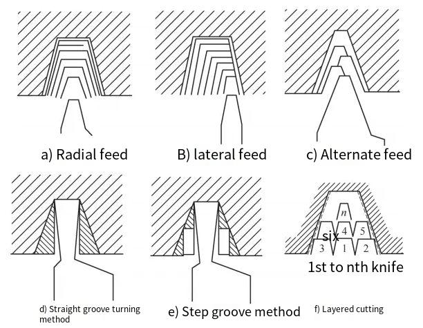
The large pitch and deep groove profile require a tailored cutting strategy to manage cutting forces and maintain surface quality. Several feed methods were evaluated, including radial feed, flank feed, alternating feed, straight groove cutting, stepped groove cutting, and layered cutting. The layered cutting method was selected, dividing the groove depth into multiple layers, with each layer further segmented into multiple Z-axis passes. This approach ensures that only one cutting edge is engaged at a time, reducing cutting forces, improving chip evacuation, and extending tool life.
| Feed Method | Description | Applicability |
|---|---|---|
| Radial Feed | Tool moves directly into the workpiece along the radial direction. | High cutting forces, unsuitable for deep grooves. |
| Flank Feed | Tool engages one side of the groove, reducing contact area. | Moderate reduction in cutting forces, limited for large pitches. |
| Layered Cutting | Groove depth divided into layers, with multiple Z-axis passes per layer. | Optimal for large pitch and deep grooves, minimizes forces and enhances surface quality. |
Tool Selection and Alignment
A multi-tool strategy was adopted to separate roughing and finishing operations. For roughing, a square coated carbide insert (SNMM250924-TP FP4725) with a 45° lead angle and a 25mm cutting edge length is used to remove the majority of material. The 45° lead angle facilitates alternating engagement of the main and secondary cutting edges, reducing tool wear. For finishing, a 32mm-diameter round insert (RCMX3209M0RH KC9220) ensures precise root radius formation and high surface quality.
Accurate tool alignment is critical for multi-tool machining within the same spiral groove. The following principles are applied:
- Reference Groove Machining: Annular grooves for tool entry and exit are machined first, serving as a reference for tool alignment and CNC encoder control.
- Roughing Tool Alignment: The roughing tool’s cutting edge (tool tip) is aligned with the Z-axis using the annular groove, and the X-axis is aligned with the workpiece’s outer diameter.
- Finishing Tool Alignment: The finishing round insert uses its arc center for Z-axis alignment and the tool tip for X-axis alignment.
- Tool Holder Consistency: Both roughing and finishing tools use identical tool holder dimensions to maintain consistent cutting edge height, simplifying tool changes.
CNC Programming and Machining Sequence
The machining sequence is programmed using a Siemens CNC system, with the annular groove center set as Z0 and the workpiece outer diameter as X0. The process begins with scribing a shallow (0.05mm) spiral line on the workpiece surface to guide subsequent cuts. The CNC machining sequence is as follows:
- Roughing of the first thread (SF=0).
- Roughing of the second thread (SF=180).
- Finishing of the first thread.
- Finishing of the second thread.
Roughing uses a spindle speed of 10 RPM, with a feed rate of 10mm/rev per layer in the diameter direction. Finishing employs a feed rate of 0.8–1mm/rev. The layered cutting approach divides the groove depth into multiple passes, with the roughing tool removing material in increments (e.g., R1=19, 14, 9, 4mm) and corresponding X-axis positions (X=-10, -20, -30, -40, -48mm). The macro program for roughing is as follows:
G90 G95 G54 M03 S10 F1
R1=19
SS: G0 Z=R1
X-10
G33 Z-2400 K200 SF=0
G04 F1
G0 X20
Z0
R1=R1-1
REPEAT SS P=38
M05
M30
For finishing, the round insert employs alternating flank feeds initially, transitioning to radial feeds as the groove deepens. The macro program for finishing is:
G90 G95 G54 M03 S10 F1
R1=0
SS: G0 Z8
X=-R1
G33 Z-2400 K200 SF=0
G04 F1
G0 X20
Z0
G0 Z-8
X=-R1
G33 Z-2400 K200 SF=0
G04 F1
G0 X20
Z0
R1=R1+0.8
REPEAT SS P=20
M05
M30
To reduce non-cutting time, manual single-pass programming is used during finishing, with cycle counts adjusted based on cutting depth.
Key Technical Considerations
Several technical considerations ensure the reliability and repeatability of the machining process:
- Spindle Speed Consistency: Maintaining a constant spindle speed (10 RPM) prevents thread pitch errors due to servo system lag during multi-pass cutting.
- Precision Tool Alignment: Tool alignment uses a 0.001mm handwheel pulse generator setting for X- and Z-axis approaches to ensure accuracy.
- Finishing Pass Strategy: The round insert finishes the groove’s straight sections (bottom and sides) through multiple Z- and X-axis passes, ensuring dimensional accuracy and surface quality.
Process Outcomes
The optimized process significantly improves CNC machining efficiency and quality. Compared to the initial single-tool method (120 hours), the multi-tool, layered cutting approach reduces CNC machining time by approximately four times. Compared to the single forming tool method, efficiency improves by 1.5 times. The square coated carbide insert ensures efficient roughing, while the round insert guarantees precise root radius formation and superior surface finish. The process is robust, repeatable, and adaptable to similar large-scale sleeve components with deep spiral grooves.
| Method | Machining Time | Surface Quality | Tool Life |
|---|---|---|---|
| Single Tool Profiling | 120 hours | Poor | Low |
| Single Forming Tool | ~80 hours | Moderate | Moderate |
| Multi-Tool Layered Cutting | ~30 hours | High | High |

Conclusion
The optimized machining process for deep rectangular spiral grooves on large-scale sleeve components demonstrates a systematic approach to overcoming the challenges of large pitch, deep profiles, and high surface quality requirements. By integrating multi-tool strategies, layered cutting, precise tool alignment, and tailored CNC programming, the process achieves a significant reduction in machining time while ensuring dimensional accuracy and surface quality. This methodology provides a reliable and efficient solution for similar applications in heavy machinery manufacturing.