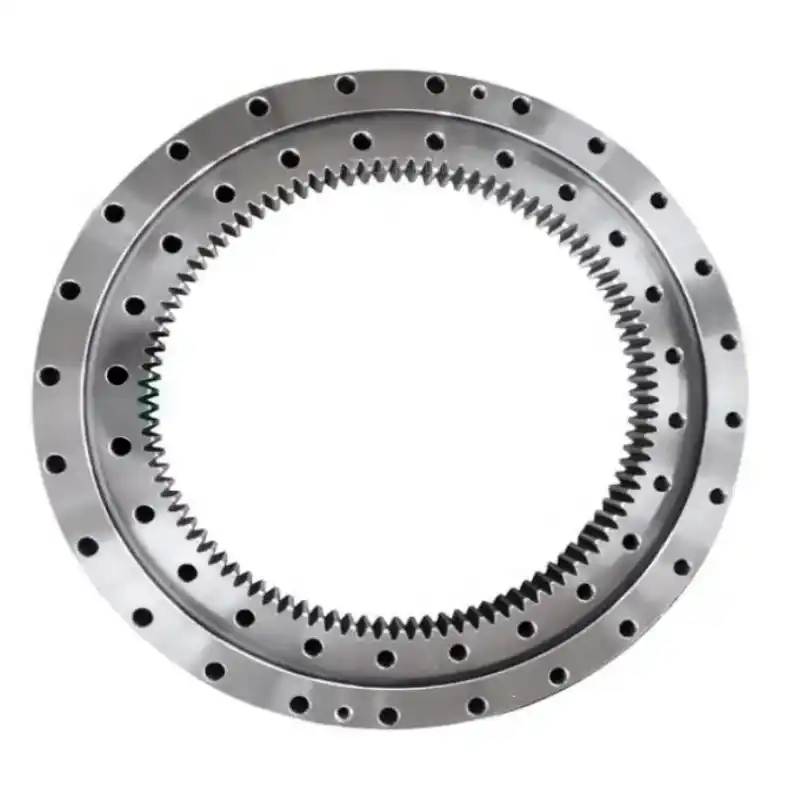
Large internal gear rings, critical components in wind turbine gearboxes, require high positional accuracy for pin holes to ensure interchangeability with the gearbox housing, enhance bolt safety, and minimize fracture risks. These rings, often thin-walled and heavy, are prone to deformation, posing significant machining challenges. This article outlines a systematic approach to achieve high positional accuracy in pin hole machining for large wind turbine internal gear rings, integrating deformation pre-control, symmetric offset machining, face-to-face alignment, and optimized inspection methods.
Positional Accuracy Definition
Positional accuracy, or position tolerance, defines the permissible deviation of a feature’s actual position from its ideal position, determined by datum references and theoretical dimensions. For a pin hole, the ideal axis centerline coordinates relative to datum planes X and Y are (a, b), while the actual coordinates are (x, y). The deviation is calculated as f_x = x - a and f_y = y - b. The positional error, W, is given by W = 2√(f_x² + f_y²). This metric quantifies the allowable positional variation, ensuring precise alignment during assembly.
Technical Requirements for Internal Gear Rings
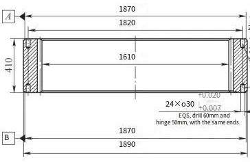
The internal gear ring under study has specific dimensional and machining requirements. Pin holes demand a positional accuracy of φ0.08 mm, with uniform distribution on both faces and an angular deviation between faces ≤0.05°. Surface roughness must achieve Ra = 1.6 μm. Traditional machining methods, evaluated using a coordinate measuring machine (CMM) with datums A and B and polar coordinate inspection, yielded positional accuracies ranging from φ0.051 mm to φ0.091 mm, often exceeding the tolerance limit.
Optimized Machining Techniques
To meet stringent positional accuracy requirements, the machining process was enhanced through four key techniques, each addressing specific aspects of deformation, alignment, and error accumulation.
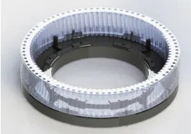
Deformation Pre-Control Technique
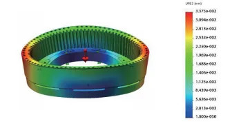
Given the thin-walled structure and significant weight of the gear ring, deformation during handling and machining is a primary concern. A specialized fixture was designed, incorporating eight evenly distributed positioning pins and four limit blocks, as determined through finite element analysis (FEA). This fixture minimizes stress concentration and controls deformation. The FEA results indicated that the maximum deformation during lifting was reduced from 0.059 mm to 0.034 mm when using the fixture. Additionally, the fixture enhances clamping efficiency, improving overall rigidity and stability. The displacement distribution during lifting, with and without the fixture, is summarized below:
| Condition | Maximum Deformation (mm) |
|---|---|
| Gear Ring Only | 0.059 |
| Gear Ring with Fixture | 0.034 |
Symmetric Offset Machining Technique
The machining was performed on a turn-mill machining center with a worktable rotational axis positioning accuracy of ±5″ and repeatability of ±2.5″. To mitigate cumulative rotational errors, the conventional sequential hole machining was replaced with a symmetric offset approach. This method distributes machining stresses symmetrically, reducing abnormal deformation. Key parameters of the two approaches are compared below:
| Parameter | Sequential Machining | Symmetric Offset Machining |
|---|---|---|
| Stress Distribution | Asymmetric | Symmetric |
| Deformation Control | Poor | Enhanced |
| Error Accumulation | High | Reduced |
This technique effectively balances machining forces, ensuring consistent positional accuracy across all pin holes.
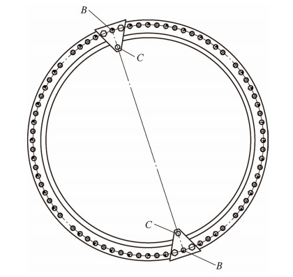
Face-to-Face Alignment Technique
To achieve the required angular deviation of ≤0.05° between pin holes on opposite faces, a face-to-face alignment technique was developed using a custom alignment plate. Traditional methods, relying on scribing to locate corresponding holes after flipping the workpiece, introduced significant angular errors due to inaccuracies in identifying intersection points. The new method involves the following steps:
- Precision bore the pin holes on one face and secure the alignment plate using the gear ring’s threaded holes.
- Identify point C, where the alignment plate and pin hole B are collinear, and precision bore hole C.
- Flip the gear ring and locate the two C holes to establish the CC line, ensuring alignment of the centerlines on both faces.
This approach reduced angular deviation by 50% to 60%, significantly improving alignment precision.
Optimized Inspection and Evaluation
Inspection accuracy was enhanced by standardizing the datum references (the plane containing the pin holes and the outer diameter of the corresponding flange) and specifying the starting hole for measurement. A uniform number of data points was collected, and the minimum zone method was applied for evaluation. By rotating the initial coordinate system and optimizing measurement data, positional accuracy was recalculated to minimize errors. Post-optimization, positional accuracy improved from φ0.051–0.091 mm to φ0.029–0.055 mm, consistently meeting the φ0.08 mm requirement.
Results and Validation
The optimized machining and inspection techniques were applied to a batch of identical internal gear rings. Post-machining inspection confirmed positional accuracies ranging from φ0.029 mm to φ0.055 mm, well within the specified tolerance. The improvements also reduced stress concentration, enhanced deformation control, and increased machining efficiency by 10% to 25%. The consistent achievement of high positional accuracy validates the effectiveness of the integrated approach.
Practical Implications
The developed methodology ensures reliable pin hole machining for large internal gear rings, improving interchangeability with gearbox housings and reducing bolt failure risks. The enhanced rigidity and stability of the gear ring during machining contribute to higher assembly precision and efficiency, facilitating maintenance in wind turbine applications. The techniques are scalable and applicable to similar thin-walled, large-diameter components in other industries.
Conclusion
The combination of deformation pre-control, symmetric offset machining, face-to-face alignment, and optimized inspection provides a robust solution for achieving high positional accuracy in pin hole machining of large internal gear rings. By addressing deformation and alignment challenges systematically, this approach ensures compliance with stringent technical requirements, enhances component reliability, and improves production efficiency. The methodology, supported by empirical data and precise technical controls, offers a comprehensive framework for manufacturers aiming to meet precision and performance standards in heavy-duty applications.