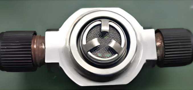
The aviation fuel solenoid valve, a critical component in aircraft fuel systems, controls fuel flow through electromagnetic and spring mechanisms. The valve's threaded joint, typically made from 1Cr17Ni2 stainless steel, ensures sealing integrity. Excessive wear or damage to this joint can compromise sealing, leading to fuel system failures that affect aircraft operation. To restore functionality, a material reduction repair method is proposed, involving machining the damaged M30×1 mm threaded joint to a smaller M28×1 mm thread. This process reduces the joint's wall thickness from 2.5 mm to 1.5 mm, raising concerns about its mechanical reliability under operational pressures. This article evaluates the reliability of this repair using theoretical calculations and finite element analysis (FEA) with CATIA software, confirming that the repaired joint meets the pressure requirements of 0.7 MPa.
1Cr17Ni2 stainless steel, a martensitic-ferritic alloy, is selected for its excellent corrosion resistance, mechanical strength, and machinability. After quenching and tempering, it performs reliably below 400°C, making it suitable for aviation, aerospace, and chemical applications. Its properties include good polishability, machinability, and weldability, which support the proposed repair method. The analysis focuses on ensuring the repaired joint maintains structural integrity under operational conditions.
Material Properties of 1Cr17Ni2 Stainless Steel
1Cr17Ni2 stainless steel is a dual-phase alloy with balanced strength and toughness, ideal for demanding environments. Its chemical composition and mechanical properties are critical for accurate reliability analysis. The material is assumed to be isotropic for simulation purposes. The key physical properties used in the analysis are:
| Property | Value |
|---|---|
| Thermal Conductivity (λ) | 20.9 W/(m·K) |
| Specific Heat Capacity (c) | 459.8 J/(kg·K) |
| Linear Expansion Coefficient (α_L) | 10.0×10⁻⁶ /K |
| Yield Strength (σ_s) | 1008 MPa |
| Young’s Modulus (E) | 2.1×10⁵ MPa |
| Poisson’s Ratio (γ) | 0.26 |
The chemical composition of 1Cr17Ni2, which influences its performance, includes elements such as chromium (16-18%), nickel (1.5-2.5%), and carbon (0.11-0.17%), ensuring corrosion resistance and mechanical stability. These properties are incorporated into the finite element model to ensure accurate stress and deformation predictions.
Repair Methodology
The repair involves machining the damaged M30×1 mm threaded joint to remove worn threads, followed by re-threading to create a new M28×1 mm joint. This reduces the wall thickness from 2.5 mm to 1.5 mm. The solenoid valve’s threaded joint seals the fuel filter’s internal cavity, which houses a filter screen and withstands an internal fuel pressure of 0.7 MPa. The repair aims to restore sealing functionality while maintaining structural integrity. The thinner wall thickness necessitates a detailed analysis to confirm that the repaired joint can withstand operational pressures without failure.
The machining process uses precision lathe techniques to ensure dimensional accuracy and surface quality of the new threads. The internal cavity, with a diameter of 23 mm, remains unchanged, and the repair focuses solely on the threaded region. The remaining valve body, with a thickness exceeding 6 mm, is considered robust and excluded from the analysis, as it is not a weak point.
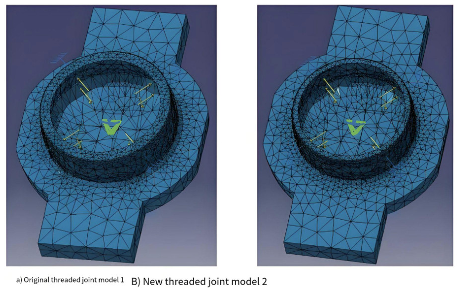
Finite Element Model Development
The finite element analysis is conducted using CATIA P3 V5 software to evaluate the stress distribution in the repaired joint. Two 3D geometric models are created: Model 1 (original M30×1 mm joint, 2.5 mm thickness) and Model 2 (repaired M28×1 mm joint, 1.5 mm thickness). To simplify the models, the threaded sections are omitted, as they contribute minimally to internal pressure resistance. The valve body is represented by an 8 mm rigid plate, reflecting its non-critical thickness.
The models are meshed using 8-node SOLID70 thermal solid elements, with a minimum mesh size of 1.5 mm × 1.5 mm × 2 mm. A transition from dense to sparse meshing optimizes computational efficiency while maintaining accuracy in critical areas. The mesh configuration ensures reliable stress and deformation calculations under the applied pressure of 0.7 MPa.
Theoretical Wall Thickness Calculation
To assess the structural reliability of the repaired joint, theoretical calculations are performed based on aircraft design standards, treating the threaded joint as a thin-walled conduit. The minimum wall thickness is calculated using two formulas, depending on the thickness-to-diameter ratio:
- For wall thickness ≥ 0.1 × outer diameter:
δ_min = (p × d) / (2 × σ_b)
where δ_min is the minimum wall thickness (mm), p is the working pressure (0.7 MPa), d is the inner diameter (23 mm), and σ_b is the material’s tensile strength (assumed 1200 MPa for 1Cr17Ni2). - For wall thickness ≤ 0.05 × inner diameter:
δ_min = D × {1 - [(σ_b - p_d) / (σ_b + p_d)]^0.5} / 2
where D is the outer diameter (28 mm for Model 2), and p_d is the burst pressure (4 × working pressure = 2.8 MPa).
For Model 1 (2.5 mm thickness), the thickness is close to 0.1 × outer diameter, yielding δ_min = 0.16 mm. For Model 2 (1.5 mm thickness), the thickness is slightly above 0.05 × inner diameter, yielding δ_min = 0.18 mm. Both calculated minimum thicknesses are significantly less than the actual thicknesses, indicating a safety margin.
Burst pressure is verified using the formula:
p_min = σ_b × (d / δ_min + 1) / [0.5 × (d / δ_min)² + d / δ_min + 1]
For Model 1, p_min = 2.83 MPa; for Model 2, p_min = 3.18 MPa. Both exceed the required burst pressure (2.8 MPa), confirming that the wall thicknesses satisfy operational requirements.
Further calculations for the sealing cavity (d = 23 mm) show that the original joint (2.5 mm) has a burst pressure of 186 MPa (ratio to working pressure: 265.7), and the repaired joint (1.5 mm) has a burst pressure of 117 MPa (ratio: 167). Both exceed the minimum requirement of 4 times the working pressure, validating the repair’s adequacy.
Stress Analysis Using Finite Element Method
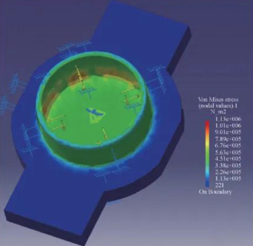
The FEA is performed in CATIA P3 V5, with 1Cr17Ni2 material properties defined in the material library. Both models undergo identical chamfering and meshing to ensure comparability. A static pressure of 0.7 MPa is applied to the inner surface of the sealing cavity. The stress distribution is analyzed to determine the maximum von Mises stress.
For Model 2 (repaired joint), the maximum von Mises stress is 1.48 MPa, significantly below the material’s yield strength (1008 MPa) and tensile strength (1200 MPa). This indicates that the repaired joint experiences negligible plastic deformation and is far from structural failure. Model 1 shows even lower stresses due to its thicker wall, but the repaired joint’s performance is sufficient for operational demands. The stress distribution confirms uniform load-bearing capacity, with no localized stress concentrations that could lead to failure.
Validation of Repair Reliability
The combined theoretical and FEA results demonstrate the reliability of the material reduction repair. The theoretical calculations confirm that the minimum wall thickness of the repaired joint (1.5 mm) exceeds the required δ_min (0.18 mm), and the burst pressure (117 MPa) is well above the operational requirement. The FEA further validates that the maximum stress (1.48 MPa) is a small fraction of the material’s yield strength, ensuring no risk of deformation or failure.
The repair method preserves the valve’s sealing functionality while maintaining structural integrity. The use of 1Cr17Ni2 stainless steel supports the repair’s feasibility due to its machinability and strength. The analysis accounts for the operational pressure of 0.7 MPa, ensuring that the repaired joint performs reliably in the aircraft fuel system.
Conclusion
The material reduction repair of the aviation fuel solenoid valve’s threaded joint, reducing the thread from M30×1 mm to M28×1 mm, is structurally reliable. Theoretical calculations show that the repaired joint’s wall thickness and burst pressure exceed design requirements. Finite element analysis confirms that the maximum stress under operational conditions is well below the material’s yield strength, ensuring no plastic deformation or structural failure. The repair method effectively restores the valve’s functionality while maintaining safety and reliability, validated through rigorous theoretical and computational methods.