
The machining of human bone models is critical in medical applications, as their precision directly impacts treatment outcomes. While 3D printing is mature in some regions, its high material and processing costs limit widespread adoption. This study addresses the challenge of modeling and machining complex, irregular human bone structures using advanced five-axis CNC technology. The process involves CT imaging for data acquisition, UG software for 3D modeling, PowerMILL for toolpath generation, Vericut for simulation, and an i5 AC cradle-type five-axis CNC machining center for production. This approach reduces processing time, enhances efficiency, and improves product quality while lowering medical costs.
Process Overview
Human bone models exhibit irregular shapes, non-uniform surface distribution, and significant side distortions, making them challenging to machine. The process begins with CT scans to obtain accurate bone geometry, followed by reverse engineering in UG to create a 3D model. The maximum dimensions of the model are φ78 mm × 80 mm (excluding the base), featuring complex surfaces and arc transitions. The material chosen is a φ80 mm nylon rod, processed on an i5M8.4 five-axis CNC machine with a maximum spindle speed of 12,000 rpm and a precision of 0.005 mm. The machining strategy includes three-axis fixed-axis roughing, 3+2 axis semi-finishing, and five-axis finishing, ensuring high accuracy and efficiency.
Three-Axis Fixed-Axis Rough Machining
Three-axis fixed-axis rough machining is employed to remove bulk material efficiently. The strategy fixes the tool axis and A/C axis rotation angles, transforming the five-axis machine into a conventional three-axis vertical machining center. This approach enhances processing efficiency for the initial material removal phase. The model is divided into four regions for machining, using Post1 and Post2 as coordinate systems for the first and second sides, respectively. To prevent tool chatter and deflection due to insufficient support at thin-walled sections, machining is restricted to 20–30 mm above the model’s center for the first two sides. This leaves a 40–60 mm thick support base, mitigating vibration. The third and fourth sides are machined using Post3 and Post4 coordinate systems, extending 2–5 mm below the centerline to ensure complete material removal without tool chatter, thus improving machining quality.
3+2 Axis Semi-Finishing
The 3+2 axis machining strategy fixes the worktable at specific angles, allowing the tool to process 3D surfaces without continuous axis movement. The i5 AC cradle-type five-axis CNC machine tilts the model to a predefined position (e.g., A = -45°, C = 0°) for machining, as shown in the process setup. The tool moves along X, Y, and Z axes, with the A/C axes adjusting as needed for different regions. This method approximates curved surfaces as planar, tilting the tool axis to avoid zero cutting speed, which enhances surface quality. The feed rate (vf) and tool axis inclination angle (α) relative to the surface normal are optimized to achieve consistent cutting performance. This approach removes undercuts inaccessible in three-axis machining, reducing residual material for the subsequent finishing stage.
Five-Axis Finishing
Five-axis finishing addresses the irregular shapes, non-uniform surfaces, and significant side distortions of human bone models, including undercut regions at the top. Unlike three-axis machining, which requires multiple fixtures and repeated clamping, five-axis machining completes all operations in a single setup, reducing positioning errors and fixture costs. The i5 system’s AC cradle-type configuration enables simultaneous control of X, Y, Z, A, and C axes. PowerMILL supports five projection finishing strategies: point projection, linear projection, plane projection, curve projection, and surface projection. For this model, point projection and linear projection finishing are selected due to their suitability for the complex geometry. These strategies ensure uniform material removal and high surface quality, significantly improving machining efficiency and precision.
Toolpath Generation and NC Code Processing
Toolpath generation is performed using PowerMILL, tailored to the model’s complex geometry. The coordinate system for five-axis machining differs from three-axis setups, with the X and Y origins at the C-axis center and the Z origin at the intersection of the A and C axes. During post-processing, NC parameters are configured to align the model’s coordinate system with the machine’s output coordinate system. For end mills, the tool center is selected as the tool position point, while for ball-end mills, the tool tip is used. The output file format is set to .NC or .TXT, ensuring compatibility with the i5 CNC system. The table below summarizes the machining parameters and strategies used.
| Stage | Strategy | Tool Type | Feed Rate (mm/min) | Spindle Speed (rpm) | Depth of Cut (mm) |
|---|---|---|---|---|---|
| Rough Machining | Model Area Clearing | End Mill | 1000–1500 | 8000–10000 | 1.0–2.0 |
| Semi-Finishing | 3+2 Axis Machining | Ball-End Mill | 800–1200 | 10000–12000 | 0.5–1.0 |
| Finishing | Point/Linear Projection | Ball-End Mill | 500–800 | 10000–12000 | 0.1–0.3 |
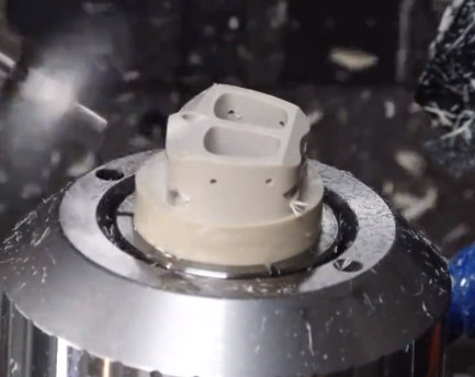
Vericut Simulation and CNC Machining
Before machining, the NC code is verified using Vericut simulation software to ensure correctness and prevent issues such as interference, overcutting, or undercutting. The simulation generates a shaded image of the machined model, confirming the toolpath’s accuracy. Once validated, the NC code is transferred to the i5 CNC machine via Distributed Numerical Control (DNC). The final product, machined from a nylon rod, achieves the required dimensional accuracy and surface quality, as shown in the completed model. The single-setup process minimizes errors and enhances efficiency, producing a high-quality human bone model suitable for medical applications.
Conclusion
This study demonstrates a systematic approach to machining irregular human bone models using five-axis CNC technology. The process leverages CT imaging, UG for 3D modeling, PowerMILL for toolpath generation, Vericut for simulation, and the i5 AC cradle-type five-axis CNC machine for production. Three-axis roughing enhances rigidity and reduces tool chatter, 3+2 axis semi-finishing removes undercuts, and five-axis finishing ensures precision for complex geometries. The single-setup machining reduces fixture requirements and positioning errors, improving efficiency and quality. This methodology provides a robust framework for machining similar complex, irregular components, offering practical value for medical and industrial applications.