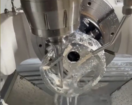
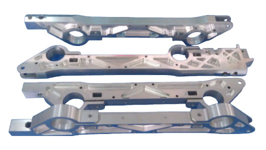
Aerospace manufacturing demands unparalleled precision and reliability due to the critical nature of its components. In CNC machining, human errors can lead to defective parts, costly rework, production delays, or even safety incidents. Aerospace parts, often produced in single-piece or small-batch discrete manufacturing, are particularly susceptible to errors caused by human factors such as skill variability, fatigue, or lapses in attention. This article examines practical error-proofing techniques—program error prevention, marking techniques, optimized process routes, and fixture design—based on extensive manufacturing experience. These methods aim to ensure high-quality production from the first attempt, enhancing quality management in aerospace manufacturing.
Understanding Human Errors in Aerospace CNC Machining
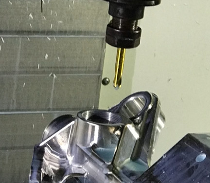
Human operators are both the most creative and least predictable element in CNC machining. Unlike CNC equipment, which executes programmed instructions consistently, human performance varies due to factors like experience, focus, and emotional state. In aerospace manufacturing, where parts are complex and tolerances are tight (often within microns), even minor errors can result in significant consequences. During the research and development phase, errors are rare due to heightened operator attention and strict protocol adherence. However, in small-batch production, complacency or habitual thinking can lead to mistakes, such as misinterpreting technical drawings, overlooking process requirements, or mishandling equipment setup. These errors may cause parts to be scrapped, require rework, or, in severe cases, lead to equipment damage or operator injury.
The objective of error-proofing is to minimize reliance on human vigilance by integrating systematic controls into the manufacturing process. By addressing common error-prone areas, aerospace manufacturers can achieve consistent quality, reduce defects, and enhance safety and efficiency.
Program Error Prevention
Program error prevention is a fundamental technique to address mistakes caused by habitual operations in CNC machining. A common error occurs when operators incorrectly set the workpiece origin, particularly for complex aerospace components like casings. Typically, casing parts have their origin set at the geometric center to evenly distribute manufacturing errors in the X and Y directions. However, certain parts require the origin to be offset to meet specific dimensional tolerances, which operators may overlook due to routine practices.
For example, consider a casing part with a total thickness tolerance greater than a critical dimension, such as 5.5 mm, which has a stricter tolerance (e.g., ±0.05 mm). Setting the origin at the geometric center may cause the 5.5 mm dimension to exceed its tolerance. To prevent this, a clear instruction can be embedded in the machining interface, such as a warning statement prompting operators to offset the origin by a specified distance (e.g., 2 mm toward one direction). This can be implemented as a pop-up alert or a comment in the CNC program, ensuring operators follow the correct setup.
Additionally, incorporating validation steps, such as requiring operators to confirm the origin setting before machining begins, enhances error prevention. Tracking features, like logging the origin coordinates in the CNC system, allow for quick verification and reduce the risk of errors due to habitual settings. This approach is simple, cost-effective, and widely applicable, making it a cornerstone of error-proofing in aerospace CNC machining.
Marking Error Prevention
Marking error prevention uses physical or visual cues to guide operators and programmers, reducing errors in origin setting, tool selection, or fixture alignment. In CNC machining, errors often arise when operators set the wrong origin, select incorrect tools, or misalign fixtures due to interruptions or multitasking. Similarly, programmers may assign tool numbers that do not match the machine’s tool library or set coordinates that conflict with the operator’s setup using edge finders.
To address these issues, marking techniques involve creating identifiable features on the workpiece to verify correct setup. For casing parts, a standard practice is to mill a shallow slot—typically 12 mm wide and 3 mm deep—in non-critical areas such as rough material, cavity interiors, or excess edge material using a rough milling cutter. This error-proofing slot serves as a visual and functional check to confirm that the origin, tool, and program are correctly set before full machining begins. If the slot is misaligned or absent, it indicates an error, halting further machining and preventing part scrapping or safety risks.
The table below outlines the key parameters for implementing marking error prevention in casing parts:
| Parameter | Beschreibung | Typical Value |
|---|---|---|
| Marking Location | Non-critical area (rough material, cavity, or edge excess) | Non-functional surface |
| Marking Dimensions | Width and depth of the error-proofing slot | 12 mm wide, 3 mm deep |
| Tool Used | Rough milling cutter for creating the slot | Standard roughing tool |
This technique is particularly effective in small-batch production, where operator fatigue or distractions are more likely to cause errors. By providing a clear visual indicator, marking error prevention ensures setup accuracy and reduces the risk of costly mistakes.
Optimized Process Route Error Prevention
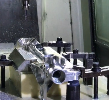
Aerospace components, such as casing parts, often feature near-symmetrical structures that are difficult to distinguish, increasing the risk of incorrect setup during machining. For example, a casing part with five faces requiring machining, processed on a three-axis vertical machining center, may need multiple setups (at least five clampings) to complete all features. Symmetrical features, such as M5x0.5 mm threaded holes on the left and right sides, can be easily confused, especially when the dimensional difference is minimal (e.g., 0.5 mm). Additionally, spatial constraints may require specific features, like threaded holes, to be machined before internal cavities to avoid interference.
The original process route for such a part might involve: (1) CNC machining to mark threaded hole positions on the left view, (2) marking hole positions on the right view, (3) manual drilling and tapping of M5x0.5 mm threaded holes, (4) CNC machining of the bottom view, (5) machining of the rear view, and (6) machining of the front view. Due to the near-symmetry of the left and right views, operators frequently misalign the part, leading to incorrect setups and scrapped parts. Measuring tools alone are insufficient in small-batch production, as the 0.5 mm difference is difficult to detect without meticulous inspection.
An optimized process route addresses this by prioritizing a distinguishable feature early in the sequence. The revised route is: (1) CNC machining of the bottom view (which is asymmetrical and easily identifiable), (2) marking threaded hole positions on the left view, (3) marking hole positions on the right view, (4) manual drilling and tapping, (5) machining of the rear view, and (6) machining of the front view. By machining the asymmetrical bottom view first, it serves as a clear reference for subsequent setups, significantly reducing the likelihood of misalignment errors.
This optimization leverages the part’s unique geometry to guide operators, ensuring correct orientation during clamping and minimizing errors without requiring additional equipment or complex procedures.
Fixture Design for Error Prevention
Fixture design is a powerful error-proofing strategy for parts with near-identical features, such as casing cover plates. Aerospace casings often include a main body and two thin cover plates (approximately 1 mm thick) secured with screws to ensure sealing. The upper and lower cover plates may have identical outer dimensions but differ in specific hole positions, such as a 22.5 mm hole on the upper plate versus a 25.5 mm hole on the lower plate—a 3 mm difference. Without clear differentiation, these plates are easily confused during machining.
The standard machining process for cover plates includes: (1) preparing material to the specified thickness, (2) wire cutting the outer shape, (3) CNC machining to mark hole positions, and (4) manual drilling and countersinking. After wire cutting, the absence of machined holes makes the plates indistinguishable, leading to errors where the total number of plates is correct, but the quantities of upper and lower plates are mismatched (e.g., one extra upper plate and one fewer lower plate). In batch production, sampling inspections often fail to detect this issue, necessitating full inspections, which increase costs and delays.
Initial improvements involved separate packaging and processing of the two plate types, which reduced errors but did not eliminate them due to miscounting during packaging. To address this comprehensively, a synchronized machining fixture was designed to process both cover plates simultaneously in a single setup. The fixture ensures that the upper and lower plates are clamped together, with hole positions marked in one CNC operation, guaranteeing a matched quantity of each plate type.
The table below compares the original and improved processes for cover plate machining:
| Process Step | Original Method | Synchronized Fixture Method |
|---|---|---|
| Vorbereitung des Materials | Thickness prepared per drawing | Unchanged |
| Outer Shape Cutting | Wire cutting | Unchanged |
| Hole Positioning | Separate CNC machining for each plate type | Simultaneous CNC machining for both plates |
| Manual Drilling | Separate drilling and countersinking | Unchanged |
| Inspektion | Full inspection required | Sampling inspection sufficient |
This fixture eliminates quantity mismatches, reduces inspection workload, and has been praised by operators and inspectors for its reliability and efficiency. By addressing the root cause of errors, the fixture ensures consistent production quality.
Schlussfolgerung
Error-proofing techniques—program error prevention, marking, optimized process routes, and fixture design—are essential for minimizing human errors in aerospace CNC machining. These methods address common issues in single-piece and small-batch production, such as incorrect setups, tool mismatches, and part confusion, ensuring high-quality output from the first attempt. By integrating these systematic, experience-based strategies, aerospace manufacturers can enhance quality control, reduce defects, and improve safety and efficiency. These techniques, grounded in practical application, provide a robust framework for meeting the stringent demands of aerospace manufacturing.