Wire Electrical Discharge Machining (Wire EDM) is a critical technology in advanced manufacturing, known for its high precision and ability to process complex shapes in conductive materials. This article provides a comprehensive analysis of the factors influencing Wire EDM cutting speed, focusing on process parameters and machining paths. Through experimental data and practical insights, we explore how to optimize these factors to enhance machining efficiency while maintaining quality, based on trials conducted using the DKB280 Wire EDM machine.
Wire EDM Machining Principle
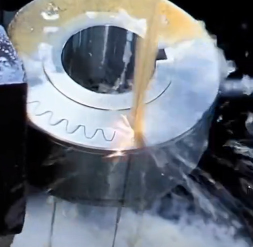
Wire EDM is a non-traditional machining process that uses electrical energy to remove material. A continuously moving thin metal wire, serving as the tool electrode, erodes material from the workpiece through pulsed electrical discharges. These discharges occur in a dielectric fluid, typically deionized water or specialized cutting fluid, which also flushes away debris.
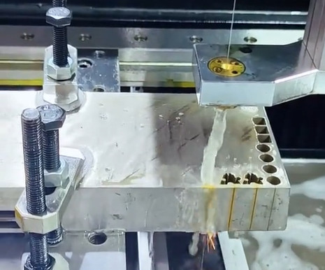
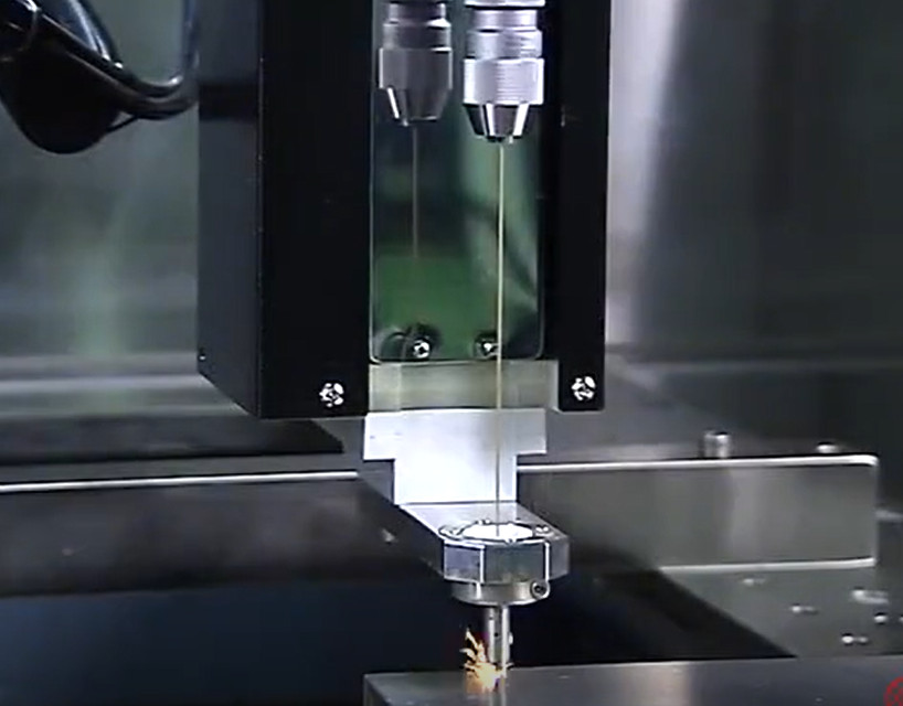
The process involves a workpiece mounted on a CNC-controlled table and a wire electrode, typically molybdenum or brass, guided by rollers and driven by a wire storage drum. The CNC system directs the table’s movement in the X and Y directions to form the desired shape. Discharges between the wire (negative electrode) and the workpiece (positive electrode) create localized high temperatures, melting or vaporizing material, which is then removed by the cutting fluid.
Wire EDM machines are categorized into three types: slow wire, fast wire, and medium wire. Slow wire machines achieve precision up to 0.001 mm with surface roughness Ra < 0.8 μm. Medium wire machines combine high-speed wire movement (8–12 m/s) for roughing and low-speed (1–3 m/s) for finishing, balancing efficiency and precision.
Key features of Wire EDM include:
- No significant mechanical cutting forces, enabling machining of any conductive material regardless of hardness.
- Capability to machine small holes and complex shapes, though blind holes are not feasible.
- Minimal wire wear, ensuring high precision.
- Narrow kerf, reducing material waste.
- Programmable CNC control for automated and adjustable machining.
Factors Influencing Wire EDM Cutting Speed
Cutting speed in Drahterodieren is defined as the area processed by the wire’s centerline per unit time (mm²/min). Several factors influence this metric, including process parameters, workpiece material, cutting fluid properties, machining path, and environmental conditions. This analysis focuses on process parameters and machining paths, as they are critical and controllable factors in production settings.
Experiments were conducted using a DKB280 Wire EDM machine with a machining range of 280 mm × 360 mm × 400 mm, comprehensive accuracy of 0.01 mm, and a maximum cutting speed of 120 mm²/min. The electrode wire was a 0.18 mm molybdenum wire, and the workpiece material was ZK10UF-1 hard alloy. The cutting fluid concentration was maintained at 10%.
Impact of Process Parameters on Cutting Speed
Process parameters significantly affect both cutting speed and surface quality. These include pulse width, pulse interval, peak current, voltage, tracking feed rate (frequency value), amplifier power, wire speed, and wire tension. The following sections analyze the effects of key parameters based on experimental results.
Pulse Width
Pulse width, the duration of voltage application between the wire and workpiece (measured in μs), directly influences discharge energy. Experiments varied pulse width while keeping other parameters constant. The results are summarized in the table below:
| Pulse Width (μs) | Cutting Speed (mm²/min) | Surface Roughness (Ra, μm) | Wire Wear |
|---|---|---|---|
| 10 | 80 | 0.9 | Niedrig |
| 15 | 100 | 0.85 | Niedrig |
| 20 | 120 | 0.8 | Mäßig |
| 25 | 110 | 0.9 | Mäßig |
| 30 | 90 | 1.0 | Hoch |
The data shows that cutting speed increases with pulse width up to 20 μs, reaching a peak of 120 mm²/min, after which it declines due to excessive energy causing unstable discharges and increased wire wear. A pulse width of 20 μs provides the optimal balance of speed and quality for machining ZK10UF-1 hard alloy on the DKB280 machine.
Pulse Interval
Pulse interval, the time between pulses (measured in μs), affects discharge frequency and debris removal. A smaller interval increases discharge frequency, potentially boosting cutting speed, but insufficient intervals hinder debris clearance, causing instability. Experimental results are shown below:
| Pulse Interval (μs) | Cutting Speed (mm²/min) | Stability | Surface Quality |
|---|---|---|---|
| 5 | 115 | Unstable | Poor |
| 7 | 118 | Stable | Gut |
| 10 | 100 | Stable | Gut |
| 15 | 85 | Very Stable | Ausgezeichnet |
A pulse interval of 7 μs yields the highest cutting speed (118 mm²/min) with stable machining and good surface quality. Shorter intervals (e.g., 5 μs) cause short circuits due to inadequate debris removal, while longer intervals reduce discharge frequency, lowering speed.
Peak Current
Peak current, the average current during discharge, determines the energy per pulse, calculated as W = t × U × I (where W is energy in joules, t is pulse duration in ms, U is voltage in volts, and I is current in amperes). Higher currents increase material removal but may degrade surface quality. Experimental results show that cutting speed rises with current up to 2.8 A, but beyond 2 A, surface micro-cracks appear, and wire wear intensifies at 4 A, risking wire breakage. A current of ≤2 A is recommended to balance speed and quality.
Tracking Feed Rate (Frequency Value)
The tracking feed rate, or frequency value, controls the wire’s advance relative to material removal. If too fast, it risks short circuits; if too slow, it reduces efficiency. Optimal tracking ensures the current remains stable, indicating balanced material removal. During non-cutting phases (e.g., moving to the starting point or returning to origin), reducing the frequency value increases feed rate, shortening idle time. For example, optimizing the feed rate for the PD-16805-M product reduced total machining time by approximately 10%.
Impact of Machining Path on Cutting Speed
The machining path, determined by CNC programming, significantly affects cutting speed and efficiency. Experiments focused on machining a 1.6 mm wide straight slot in products like PC-14502-M and PD-02501-M. The original path used a single rough cut followed by a finishing cut, but analysis revealed inefficiencies.
Four path designs were tested:
- Scheme 1: Unstable chip removal led to short circuits during the finishing cut.
- Scheme 2: Omitted a finishing segment, resulting in poor surface quality.
- Scheme 3: Produced irregular slot edges, compromising shape accuracy.
- Scheme 4: Optimized the path with a balanced rough and finish cut, ensuring stable chip removal and high surface quality.
Scheme 4 improved cutting speed by streamlining the path while maintaining precision, demonstrating that optimized programming can enhance efficiency without sacrificing quality.
Practical Considerations for Optimization
Optimizing Wire EDM cutting speed requires balancing multiple factors. Key considerations include:
- Parameter Tuning: Adjust pulse width to 20 μs and pulse interval to 7 μs for optimal speed and stability when machining ZK10UF-1 hard alloy on the DKB280 machine.
- Current Control: Maintain peak current at ≤2 A to prevent surface defects and wire damage.
- Path Optimization: Design machining paths to minimize idle time and ensure effective chip removal, as demonstrated in Scheme 4.
- Idle Phase Adjustment: Increase feed rates during non-cutting phases to reduce total machining time.
These adjustments, validated through experiments, enhance efficiency while preserving precision and surface quality, making them applicable to similar Wire EDM setups.
Schlussfolgerung
Wire EDM cutting speed is influenced by process parameters and machining paths, with pulse width, pulse interval, peak current, and tracking feed rate being critical factors. Experimental results using the DKB280 machine on ZK10UF-1 hard alloy show that a pulse width of 20 μs, pulse interval of 7 μs, and peak current of ≤2 A optimize speed and quality. Additionally, refining machining paths, as seen in Scheme 4, and adjusting feed rates during idle phases can further boost efficiency. These findings provide a practical framework for improving Wire EDM performance in precision manufacturing, ensuring high efficiency without compromising quality.