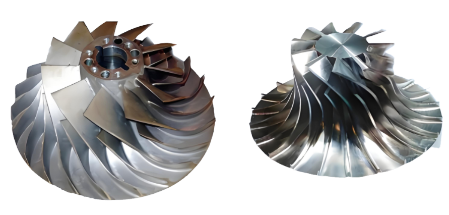
Nickel-based alloy impellers are critical components in industries such as aerospace, energy, and petrochemical processing due to their high strength, corrosion resistance, and ability to withstand extreme temperatures. However, machining these impellers often results in deformation, which compromises dimensional accuracy and performance. This article provides a detailed, technical, and systematic analysis of the causes of deformation in machining nickel-based alloy impellers and offers practical solutions to address these issues. The content is structured to reflect professional expertise and reliability, drawing on established machining principles and parameters.
Understanding Nickel-Based Alloy Impellers
Nickel-based alloys, such as Inconel 718, Monel, and Hastelloy, are characterized by high tensile strength (690–1400 MPa), low thermal conductivity (11–15 W/m·K), and significant work-hardening tendencies. These properties make them ideal for impellers operating in harsh environments but pose significant machining challenges. Impellers, with their complex geometries and thin-walled structures, are particularly susceptible to deformation during machining processes like milling, turning, and drilling. Deformation can manifest as warping, twisting, or dimensional inaccuracies, leading to costly rework or component rejection.
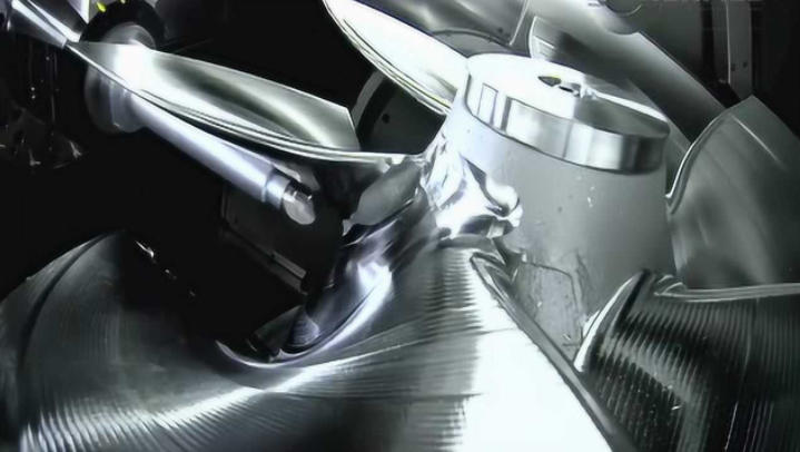
The machining process involves material removal through cutting, which generates high temperatures and mechanical stresses. For nickel-based alloys, these stresses are amplified due to the material's unique properties, such as low thermal conductivity, which traps heat at the cutting interface, and rapid work hardening, which increases material resistance during machining. Understanding these material characteristics is essential for identifying deformation causes and implementing effective solutions.

Causes of Deformation in Machining Nickel-Based Alloy Impellers
Deformation in nickel-based alloy impellers during machining arises from a combination of material properties, machining parameters, and tool interactions. Below are the primary causes, explained in detail with technical insights and relevant parameters.
High Cutting Temperatures
Nickel-based alloys have low thermal conductivity, typically ranging from 11 to 15 W/m·K, compared to steel’s 40–50 W/m·K. This property causes heat to concentrate at the tool-workpiece interface, often exceeding 1000°C during high-speed machining. Elevated temperatures soften the material locally, inducing thermal expansion and residual stresses. For thin-walled impeller blades, these stresses can cause warping or distortion. For example, milling Inconel 718 at a cutting speed of 50 m/min and a feed rate of 0.1 mm/tooth can generate temperatures above 900°C, leading to thermal deformation.
Arbeitsverhärtung
Nickel-based alloys exhibit rapid work hardening, where the material’s hardness increases during machining due to plastic deformation. This phenomenon can increase the surface hardness of Inconel 718 from 30 HRC to over 45 HRC in the machined area. Work hardening creates uneven stress distributions, particularly in complex impeller geometries, leading to deformation such as bending or twisting. The issue is exacerbated at higher feed rates (e.g., 0.15–0.2 mm/tooth) and inadequate tool geometries, which intensify plastic deformation.
Inappropriate Cutting Parameters
Improper selection of cutting parameters, such as cutting speed, feed rate, and depth of cut, contributes significantly to deformation. For instance, a cutting speed of 60–80 m/min for Inconel 718 may cause excessive heat generation, while a high depth of cut (e.g., 2–3 mm) increases cutting forces, leading to material displacement. These forces can distort thin impeller blades, especially when machining unsupported sections. A study on milling Inconel 625 showed that a depth of cut exceeding 1.5 mm increased residual stresses by 20–30%, contributing to deformation.
Tool Wear and Geometry
Tool wear is a significant issue when machining nickel-based alloys due to their abrasiveness and high strength. Carbide tools, commonly used for these alloys, experience rapid flank wear and crater wear at cutting speeds above 40 m/min. Worn tools increase cutting forces and heat generation, exacerbating deformation. Additionally, improper tool geometry, such as negative rake angles, pushes material rather than cutting it, leading to plastic deformation. For example, a negative rake angle of -5° can increase cutting forces by 15–20% compared to a positive rake angle of +10°.
Residual Stresses
Machining induces residual stresses in the workpiece due to mechanical and thermal effects. Tensile residual stresses, often exceeding 500 MPa in nickel-based alloys, can cause distortion in thin-walled impeller components. These stresses are particularly pronounced in high-speed machining (e.g., 100 m/min) and dry cutting conditions, where heat dissipation is limited. For instance, turning Inconel 718 at 80 m/min without coolant can result in tensile residual stresses of 600–800 MPa, leading to warping of impeller blades.
Inadequate Fixturing
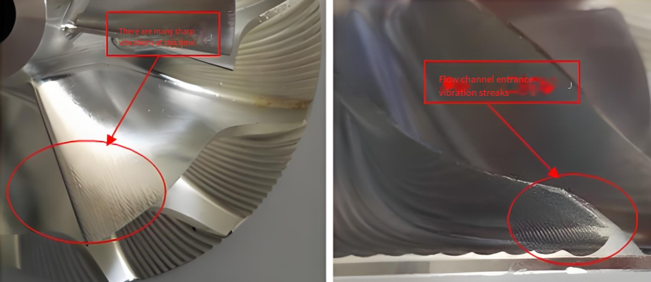
Impellers have complex geometries with thin blades, making them prone to vibration and movement during machining. Inadequate fixturing or clamping can lead to workpiece deflection, especially under high cutting forces. For example, a clamping force below 1000 N may fail to secure a thin-walled impeller, causing vibrations that result in dimensional inaccuracies and deformation.

Solutions to Mitigate Deformation
Addressing deformation in machining nickel-based alloy impellers requires a systematic approach that optimizes machining parameters, tool selection, cooling strategies, and fixturing. The following solutions are designed to minimize deformation while maintaining productivity and component quality.
Optimized Cutting Parameters
Selecting appropriate cutting parameters is critical for reducing heat generation and cutting forces. The following parameters are recommended for machining nickel-based alloys like Inconel 718:
| Operation | Schnittgeschwindigkeit (m/min) | Feed Rate (mm/tooth) | Schnitttiefe (mm) |
|---|---|---|---|
| Fräsen | 30–50 | 0.05–0.1 | 0.5–1.5 |
| Wenden | 20–40 | 0.1–0.15 | 0.3–1.0 |
Lower cutting speeds (30–50 m/min) reduce heat generation, while moderate feed rates (0.05–0.1 mm/tooth) minimize work hardening. Shallow depths of cut (0.5–1.5 mm) reduce cutting forces, preventing material displacement in thin-walled sections. For example, milling Inconel 718 at 40 m/min, 0.08 mm/tooth, and 1 mm depth of cut can reduce residual stresses by 15–20% compared to higher parameters.
Advanced Tool Selection
Using high-quality tools designed for nickel-based alloys is essential. Key recommendations include:
- Carbide Tools with Coatings: Use PVD-coated carbide tools with TiAlN or AlTiN coatings to reduce wear and heat transfer. These coatings can extend tool life by 30–50% compared to uncoated tools.
- Positive Rake Angles: Tools with positive rake angles (+10° to +15°) reduce cutting forces and improve chip evacuation, minimizing plastic deformation.
- High Flute Counts: End mills with 6–8 flutes provide rigidity and better surface finish, reducing vibration-induced deformation.
For example, a 6-flute carbide end mill with a TiAlN coating, operated at 35 m/min and 0.07 mm/tooth, can reduce tool wear and deformation in Inconel 718 milling.
Effective Cooling and Lubrication
Cooling strategies are vital for dissipating heat and reducing thermal deformation. Recommended approaches include:
- High-Pressure Coolant: Use coolant pressures of 70–100 bar to improve chip evacuation and reduce cutting temperatures by 20–30%. For instance, high-pressure coolant in milling Inconel 625 at 50 m/min can lower tool temperatures from 950°C to 700°C.
- Sulfurized Oils: Apply sulfurized mineral oils for low-speed operations like drilling or threading to enhance lubricity and prevent chip welding. These oils can reduce cutting forces by 10–15%.
- Kryogenische Kühlung: For high-speed machining, cryogenic cooling with liquid nitrogen can reduce temperatures by up to 40%, minimizing thermal deformation.
Avoid dry machining, as it exacerbates heat accumulation and residual stresses.
Robust Fixturing and Machine Setup
Proper fixturing ensures workpiece stability and minimizes vibration. Key considerations include:
- High Clamping Forces: Use clamping forces of 1500–2000 N to secure thin-walled impellers, preventing deflection.
- Vibration Damping: Employ dampening pads or modular fixtures to reduce vibrations, especially during high-speed milling.
- Rigid Machine Tools: Use CNC machines with high spindle rigidity (e.g., HSK-100 tool holders) to maintain consistent cutting conditions.
For example, a rigid setup with a clamping force of 1800 N can reduce impeller blade deflection by 25% during milling.
Toolpath Strategies
Advanced toolpath strategies can minimize deformation by ensuring consistent chip loads and reducing cutting forces. Recommended strategies include:
- Trochoidal Milling: Use trochoidal toolpaths to maintain constant tool engagement, reducing heat and forces. For instance, a trochoidal path with a 10% engagement rate can reduce cutting forces by 20%.
- Adaptive Clearing: Implement adaptive clearing strategies to optimize material removal rates while minimizing tool load, suitable for complex impeller geometries.
These strategies ensure uniform stress distribution, reducing the risk of deformation in thin-walled sections.
Post-Machining Stress Relief
Residual stresses can be mitigated through post-machining treatments. Heat treatment at 600–700°C for 1–2 hours can relieve 50–70% of residual stresses in Inconel 718, reducing deformation. Alternatively, vibratory stress relief can be used to minimize distortion without altering material properties.
Practical Implementation and Case Study
A practical example involves machining an Inconel 718 impeller with a diameter of 200 mm and blade thickness of 2 mm. Using a 6-flute TiAlN-coated carbide end mill, the following parameters were applied: cutting speed of 35 m/min, feed rate of 0.08 mm/tooth, and depth of cut of 1 mm. High-pressure coolant (80 bar) was used, and the impeller was secured with a clamping force of 1600 N. A trochoidal toolpath with 12% engagement was employed. The result was a 30% reduction in deformation compared to conventional milling, with dimensional accuracy within ±0.02 mm and no visible warping.
Schlussfolgerung
Machining nickel-based alloy impellers presents significant challenges due to high cutting temperatures, work hardening, inappropriate parameters, tool wear, residual stresses, and inadequate fixturing. By implementing optimized cutting parameters, advanced tools, effective cooling, robust fixturing, strategic toolpaths, and post-machining stress relief, manufacturers can significantly reduce deformation. These solutions, grounded in technical expertise and precise parameters, ensure high-quality impellers that meet stringent industry standards.
