This article details the use of coordinate measuring machine (CMM) measurement techniques and reverse dimension control to achieve surface profile tolerance for a complex thin-walled machined part, specifically an engine component made from 6061-T651 aluminum alloy. The part, with a final wall thickness of 2.5mm, demands high precision, requiring surface profile tolerances of 0.25mm for specific datum planes. Initial production trials showed a low yield rate, with only 10% of parts meeting specifications after CNC machining and 20% after rework. Measurement data indicated inconsistent results with no clear pattern, necessitating a systematic approach to identify and control factors affecting surface profile tolerance. Through reverse dimension control, process optimization, and precise CMM measurement, the production process was refined to meet the stringent 0.25mm tolerance requirement, ensuring compliance with customer specifications.
Part Specifications
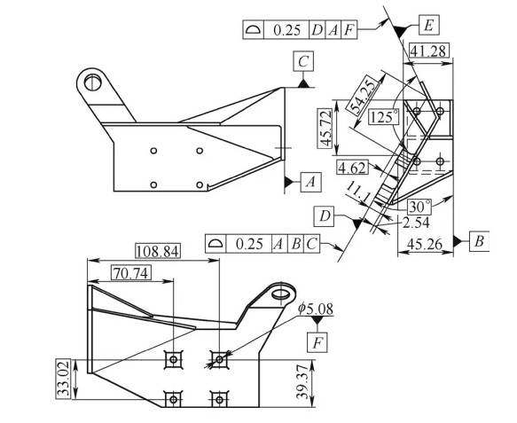
The part is manufactured from a 76.2mm thick 6061-T651 aluminum alloy plate, conforming to AMS-QQ-A-250/11 standards. After machining, the wall thickness is reduced to 2.5mm, making the part susceptible to deformation. Approximately 65% of the part’s dimensions are spatial, requiring precise control over multiple datum planes and features. The key datum planes and their relationships are as follows:
- Datum A: A side plane with four holes, serving as the primary datum for other features.
- Datum B: The back face, perpendicular to Datum A.
- Datum C: The upper edge, also perpendicular to Datum A.
- Datum D: A composite plane formed by four stepped surfaces, with a 30° spatial angle relative to Datum B.
- Datum E: An inclined stepped side face at the upper right, with a 125° spatial angle relative to Datum D.
- Datum F: The center hole of the upper right step, critical for positioning.
The part undergoes two surface treatments post-machining: chemical oxidation with Alodine 600 on Datums A, D, and E, and chromic acid anodizing on the remaining surfaces. The surface profile tolerance for Datum D relative to Datums A, B, and C, and for Datum E relative to Datums D, A, and F, must be maintained at 0.25mm after surface treatment.
Initial Challenges and Analysis
During initial production, only 2 out of 20 parts met the 0.25mm surface profile tolerance after CNC-Bearbeitung, yielding a 10% pass rate. After rework, the pass rate increased to 20% (4 parts). CMM measurement data revealed surface profile values ranging from 0.16mm to 0.28mm for Datum D and 0.23mm to 0.42mm for Datum E, with no consistent pattern. The spatial angles of 30° (Datum D to Datum B) and 125° (Datum E to Datum D) varied between 29°49′32″ to 29°58′06″ and 124°42′12″ to 125°16′34″, respectively. Datum D’s flatness ranged from 0.02mm to 0.08mm.
The primary issue was the absence of a unified machining and clamping datum, compounded by the part’s thin-walled structure, which led to deformation during machining and surface treatment. The original process involved removing temporary process steps before surface treatment, requiring secondary machining of Datums A, D, and E post-anodizing. This step introduced positional inaccuracies due to deformation, contributing to the inconsistent surface profile measurements.
Reverse Dimension Control Analysis
To address the low yield rate, a reverse dimension control analysis was conducted to identify and control factors affecting surface profile tolerance. The analysis focused on the positional relationships, angles, and flatness of the datum planes, with CMM measurements providing critical data for validation.
Key Factors Affecting Surface Profile
The surface profile tolerance of Datum D depends on its position relative to Datums A, B, and C, the 30° spatial angle with Datum B, and the flatness of its four composite planes. Similarly, Datum E’s surface profile is influenced by Datum D’s profile, the 125° spatial angle with Datum D, and the position of Datum F (the center hole). The critical positional relationship between Datum A and Datum F was calculated using the formula for positional tolerance:
Z = 2 × [(X - X1)² + (Y - Y1)²]^0.5
Where Z is the actual positional tolerance, X and Y are measured coordinates, and X1 and Y1 are theoretical coordinates.
The surface profile tolerance band of 0.25mm was decomposed as follows:
- Assuming negligible angle and flatness deviations, the positional tolerance band is ±0.087mm.
- With an angle tolerance of ±5″ and negligible flatness deviation, the dimensional tolerance band is ±0.07mm.
- With an angle tolerance of ±5″ and a flatness tolerance of ±0.02mm, the dimensional tolerance band is ±0.05mm.
Reverse calculations determined that to achieve a 0.25mm surface profile tolerance for Datum E, the positional tolerance for Datum F relative to Datum A must be controlled at (108.84 ± 0.087)mm and (45.72 ± 0.087)mm, and the distance from Datum D to Datum E at (4.62 ± 0.087)mm. When considering the 30° ± 5″ angle, the tolerances tighten to ±0.06mm for these dimensions. Additionally, Datum D’s flatness must be controlled within 0.04mm, and the spatial angles must be maintained at 30° ± 2″ (Datum D to Datum B) and 125° ± 8″ (Datum E to Datum D).
Revised Process Route
The original process route was revised to eliminate secondary machining of Datums A, D, and E after surface treatment, as it introduced positional errors due to deformation. The revised process route is as follows:
- Prepare raw material blank.
- Mill hexagonal outer shape.
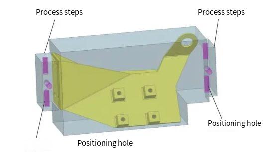
- Mill process steps and positioning holes.
- CNC rough machining of inner cavity and outer shape.
- CNC five-axis finish machining of inner cavity and outer shape.
- Wire cutting to remove process steps.
- Deburring.
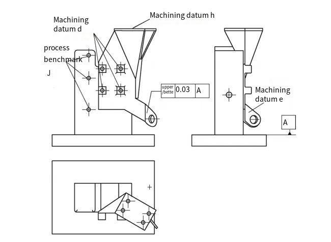
- CNC milling of Datum A, holes, and lengths.
- Deburring.
- Inspection.
- Polishing.
- Chromic acid anodizing with protection for Datums A, D, and E.
- Polishing of Datums A, D, and E.
- Alodine 600 coating on Datums A, D, and E.
- Marking.
- Final inspection.
- Stamping, packaging, and storage.
Protecting Datums A, D, and E during anodizing and using polishing instead of secondary machining ensured dimensional stability, with CMM measurements verifying compliance.
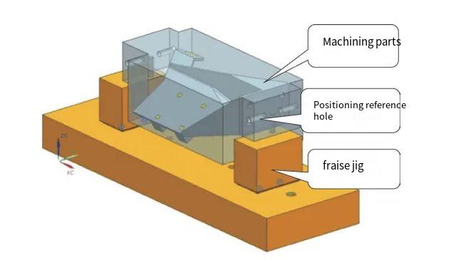
Fixture Design
A dedicated milling fixture was designed to enhance machining accuracy. The fixture uses six φ6mm positioning holes (±0.02mm tolerance) for clamping, ensuring consistent positioning during machining of inclined surfaces and steps. The fixture allows flipping the part to machine three faces, maintaining dimensional stability within 0.3mm for semi-finish machining. For Datum A, a separate fixture was designed, using three holes on Datum D for positioning and three threaded holes (Datum J) for clamping. The critical dimension of 108.84mm from Datum J to Datum A was controlled within ±0.03mm, with perpendicularity of Datum A to Datum B maintained within 0.03mm.
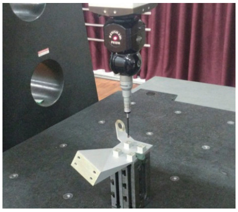
CMM Measurement Process
Post-machining measurements were conducted using a CMM with PC-DMIS CAD software. A 3D model was created to align the part’s coordinate system with design specifications. Measurement points were selected as follows:
| Datum | Measurement Points | Purpose |
|---|---|---|
| Datum A (ZC) | At least 3 points | Establish primary datum plane |
| Datum B (YC) | 2 points | Establish secondary datum plane |
| Datum C (XC) | 1 point | Establish tertiary datum point |
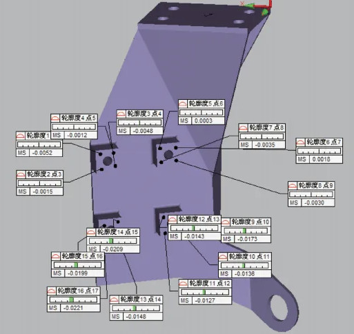
| Datum D | 4-6 points per plane (4 planes) | Measure surface profile tolerance |
The CMM compared measured points to the 3D model, yielding surface profile values of 0.04mm to 0.21mm for Datum D and 0.14mm to 0.23mm for Datum E. Spatial angles were measured at 29°59′44″ to 30°1′29″ (Datum D to Datum B) and 124°52′55″ to 124°58′12″ (Datum E to Datum D), with Datum D flatness ranging from 0.01mm to 0.03mm. All measurements met the 0.25mm tolerance requirement, validated through consistent CMM data collection.
Schlussfolgerung
Through reverse dimension control, process optimization, and precise CMM measurement, the surface profile tolerance of the complex thin-walled part was successfully controlled within 0.25mm. The introduction of process steps and positioning holes, combined with a revised process route that eliminated secondary machining post-surface treatment, ensured dimensional stability. CMM measurements validated the approach, achieving a 100% pass rate and meeting customer requirements. This systematic methodology demonstrates technical expertise and reliability in high-precision manufacturing, with CMM measurement playing a critical role in ensuring compliance.