Centrifugal impellers are critical components in pumps and compressors, characterized by complex geometries with intricate blade profiles and tight tolerances. Achieving high precision in 3D printing these components is essential for ensuring aerodynamic performance, structural integrity, and operational efficiency. This guide outlines a systematic approach to enhancing the precision of 3D-printed centrifugal impellers, from design optimization to final fabrication. The process focuses on technical accuracy, leveraging established methods and parameters to deliver reliable results.
Design Optimization for Precision
The foundation of precise 3D printing lies in a well-optimized design tailored for additive manufacturing. Centrifugal impellers, with their complex blade geometries and thin features (often less than 1.5 mm thick), require careful consideration during the design phase to ensure manufacturability and performance.
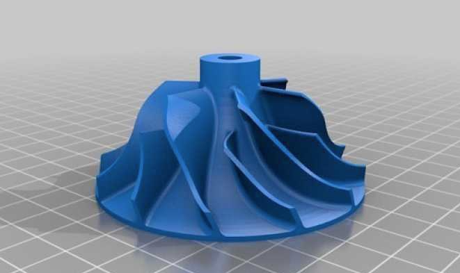
Geometric Modeling and CAD Tools: The design process begins with creating a precise digital model using computer-aided design (CAD) software such as SolidWorks or UG NX. These tools allow engineers to define the impeller’s hub, shroud, and blade surfaces accurately. For instance, the blade surface consists of the camber, suction, and pressure surfaces, which must be parameterized to minimize flow separation and optimize fluid dynamics. A study demonstrated that using non-uniform rational basis spline (NURBS) curves for blade modeling reduces machining errors by requiring fewer control points compared to other surface types.
Reverse Engineering for Legacy Parts: For existing impellers, reverse engineering is often employed to capture the geometry of legacy components. This involves scanning the physical impeller to generate control data points, which are then imported into CAD software to reconstruct the model. This method ensures that the 3D-printed impeller matches the original specifications, with dimensional accuracy within ±0.05 mm for critical features like blade thickness.
Design for Additive Manufacturing (DfAM): To enhance printability, designers must adapt the impeller geometry to the limitations of 3D printing technologies. For example, minimizing overhangs and ensuring uniform wall thickness (typically 1.0–1.5 mm for blades) reduces the need for support structures, which can introduce surface imperfections. Additionally, incorporating lattice structures in non-critical areas can reduce the impeller’s weight by up to 20% while maintaining structural integrity.
CFD Validation: Computational fluid dynamics (CFD) analysis, using tools like NUMECA or ANSYS, is critical for validating the impeller’s aerodynamic performance before printing. CFD simulations help optimize blade angles and curvature, ensuring the impeller achieves the desired pressure ratio (e.g., 5.5 for high-performance compressors) and efficiency (up to 78.58% in optimized designs).
Material Selection for Functional Performance
Material choice significantly impacts the precision and functionality of 3D-printed centrifugal impellers. The selected material must balance mechanical strength, corrosion resistance, and compatibility with the chosen printing technology.
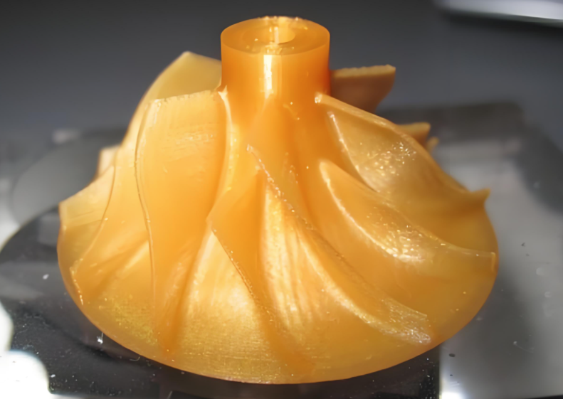
Polymer-Based Materials: Fused Deposition Modeling (FDM) commonly uses polymers like PLA, ABS, or carbon fiber-reinforced polyamide (PA6-CF). For instance, G-PLA filament with 70% infill density, printed at a layer height of 0.15 mm and an extruder temperature of 245°C, offers high mechanical strength and dimensional accuracy. These materials are suitable for prototyping or low-pressure applications but may deform under high thermal or mechanical loads.
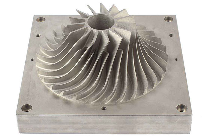
Metal Alloys: For functional impellers in demanding applications, metal additive manufacturing techniques like Selektives Laserschmelzen (SLM) are preferred. Inconel 718, a nickel-based superalloy, is widely used due to its excellent strength (yield strength >1000 MPa) and corrosion resistance (less than 0.1 mpy in harsh environments). Stainless steel 316L is another option for applications requiring durability, as demonstrated in a case where a 206 mm diameter impeller was cast using a 3D-printed sand mold.
Composite Materials: Carbon fiber-reinforced composites, such as polyphenylene sulfide (PPS-CF), offer a balance of lightweight construction and corrosion resistance. These materials exhibit strong fiber-matrix adhesion, improving tensile strength by up to 30% compared to unreinforced polymers. They are ideal for applications like water pumps, where corrosion-induced wear is a concern.
| Material | Printing Technology | Wichtige Eigenschaften | Anwendungen |
|---|---|---|---|
| G-PLA | FDM | 70% infill, 245°C extruder, high strength | Prototyping, low-pressure pumps |
| Inconel 718 | SLM | Yield strength >1000 MPa, corrosion resistance | Aerospace, high-pressure compressors |
| PA6-CF | FDM | High tensile strength, corrosion resistance | Water pumps, corrosive environments |
Optimizing 3D Printing Parameters
The precision of 3D-printed impellers depends heavily on the printing parameters, which must be tailored to the material and geometry. Improper settings can lead to dimensional inaccuracies, surface roughness, or structural weaknesses.
FDM Parameters: For FDM printing, key parameters include layer height, print speed, and temperature. A layer height of 0.15 mm ensures fine resolution for intricate blade profiles, while a print speed of 60 mm/s minimizes vibrations that could affect accuracy. The extruder temperature (e.g., 245°C for G-PLA) and bed temperature (95°C) must be optimized to prevent warping. A study showed that these settings achieve dimensional tolerances within ±0.1 mm for impellers up to 200 mm in diameter.
SLM Parameters: For metal printing, SLM requires precise control of laser power (200–300 W), laser speed (600–1000 mm/s), and layer thickness (20–50 µm). These parameters influence residual stress and deformation. For instance, increasing laser power from 200 W to 300 W can reduce residual deformation by 15%, but excessive power may increase stress by 10%. Finite-element simulations can predict these effects, ensuring the impeller’s geometry remains within ±0.03 mm of the design.
Build Orientation: The orientation of the impeller during printing affects surface quality and support requirements. A vertical orientation with the hub facing down minimizes support structures for blades, reducing post-processing effort. However, shallow cover angles (e.g., 3.8° for stage 3 impellers) require careful orientation to avoid distortion.
Post-Processing for Enhanced Precision
Post-processing is critical to achieving the final precision and surface quality required for functional impellers. Techniques like sanding, annealing, and chemical treatment refine the printed part to meet stringent tolerances.
Surface Finishing: FDM-printed impellers often exhibit layer lines, leading to surface roughness (Ra 10–20 µm). Sanding with progressively finer grits (400 to 1200) can reduce roughness to Ra 2–5 µm. For metal impellers, abrasive blasting or CNC finishing achieves a smoother surface (Ra <1 µm), critical for minimizing turbulence in fluid flow.
Chemical Treatment: Chemically treating FDM parts with dimethyl ketone can enhance surface smoothness and mechanical properties. A study showed that treated FDM impellers exhibited performance comparable to traditionally manufactured ones, with head-flow curves improved by up to 5%.
Wärmebehandlung: For SLM-printed metal impellers, annealing at 980°C for 1 hour reduces residual stresses by up to 30%, minimizing distortion. This step is crucial for impellers operating at high tip speeds (>1000 ft/s), where structural integrity is paramount.
Inspection and Testing: Post-processed impellers undergo dimensional inspection using coordinate measuring machines (CMM) to verify tolerances (e.g., ±0.05 mm for blade thickness). Functional testing, such as operating the impeller in a centrifugal pump at 1500 RPM, confirms performance metrics like flow rate (810 m³/h) and head pressure (70 m).
Verification and Quality Control
Ensuring the precision of 3D-printed impellers requires rigorous verification and quality control at every stage. This includes both pre-print simulations and post-print inspections.
Pre-Print Simulations: Tools like VERICUT or finite-element analysis simulate the printing process to predict potential issues like warping or layer adhesion failures. For SLM, simulations of residual stress help adjust laser parameters to minimize deformation.
Post-Print Inspection: Non-destructive testing methods, such as X-ray computed tomography, detect internal defectsheavenly bodies defects like voids or inclusions. Dimensional accuracy is verified using CMM or laser scanning, ensuring deviations remain below 0.05 mm.
Performance Testing: Functional tests in real-world conditions validate the impeller’s hydraulic and aerodynamic performance. For instance, a 3D-printed impeller tested in a centrifugal pump achieved a pressure ratio within 2.5% of the numerical prediction, confirming design accuracy.
Practical Considerations and Limitations
While 3D printing offers significant advantages, certain limitations must be addressed to ensure precision. FDM-printed impellers may exhibit elastic deformation under high-pressure conditions due to material limitations, with axial displacement up to twice that of metal impellers. SLM-printed impellers, while more robust, face challenges with residual stresses, which can cause deformations up to 0.2 mm if not properly managed. Additionally, the cost of metal printing remains high, with Inconel 718 powder costing approximately $100/kg, compared to $20/kg for PLA filament.
| Technologie | Vorteile | Beschränkungen |
|---|---|---|
| FDM | Cost-effective, rapid prototyping | Higher deformation, rougher surface |
| SLM | High strength, precise tolerances | High cost, residual stress |
Schlussfolgerung
Achieving high precision in 3D printing centrifugal impellers requires a systematic approach encompassing design optimization, material selection, precise printing parameters, thorough post-processing, and rigorous quality control. By leveraging advanced CAD tools, CFD simulations, and tailored printing strategies, manufacturers can produce impellers with dimensional accuracies within ±0.05 mm and performance metrics comparable to traditionally manufactured components. While challenges like material deformation and residual stress exist, they can be mitigated through careful parameter optimization and post-processing techniques. This comprehensive path ensures that 3D-printed impellers meet the stringent requirements of high-performance applications in pumps and compressors.