Impeller machining is a precision-driven process requiring accurate CNC programming to handle complex geometries, such as curved blades and tight tolerances. Coordinate offset errors can lead to dimensional inaccuracies, tool collisions, or part rejection. This guide provides a systematic, technical approach to minimizing these errors, focusing on coordinate system management, tool offset control, and error compensation techniques. The following sections detail practical methods with specific parameters to ensure high precision in impeller production.
Fundamentals of Coordinate Systems in Impeller Machining
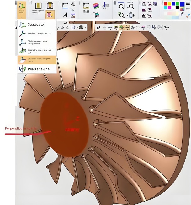
CNC machines operate using two primary coordinate systems: the Machine Coordinate System (MCS) and the Work Coordinate System (WCS). The MCS is the machine’s fixed reference, established during homing, where axes return to a zero point defined by limit switches or encoders. The WCS is user-defined, aligning with the impeller’s geometry, typically set at a datum point like the hub center or a blade feature.
In impeller machining, which often involves 4- or 5-axis CNC systems, coordinate offset errors arise from misalignments between the MCS and WCS or incorrect tool offset settings. These errors are critical due to the impeller’s complex free-form surfaces, where a 0.1 mm deviation can exceed tolerances (e.g., ±0.05 mm for aerospace impellers). The WCS is set using G-code commands like G54 to G59, which store the offset from the MCS home to the part datum in the machine’s offset register.
For example, if the impeller’s hub center is at MCS coordinates X120.000, Y180.000, Z60.000, these values are entered into the G54 register to define the WCS origin. Accurate WCS setup ensures the programmed toolpath aligns with the physical workpiece, minimizing positional errors during multi-axis machining.
Setting Work Coordinate System (WCS) Offsets
Accurate WCS setup is essential to prevent coordinate offset errors. The following steps outline a systematic process for establishing WCS offsets in impeller machining:
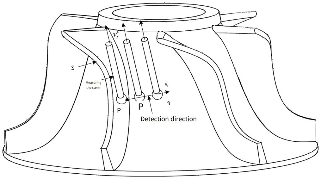
- Datum Identification: Select a reference point on the impeller, such as the hub center or a blade edge. Use a precision edge finder (accuracy ±0.005 mm) or a spindle probe to locate this point relative to the MCS.
- Offset Recording: Jog the machine to the datum and record the MCS coordinates. For instance, if the hub center is at X120.000, Y180.000, Z60.000, enter these into the G54 offset register using the machine’s control panel or G10 command (e.g.,
G10 G90 L20 P1 X120.000 Y180.000 Z60.000). - Alignment Verification: Move to the WCS zero (G54 X0 Y0 Z0) and verify the tool aligns with the physical datum. If misalignment occurs, adjust the offset values to account for fixturing errors (e.g., a 0.02 mm shift in X).
- Multi-Part Setup: For batch machining multiple impellers, assign unique WCS offsets (G54, G55, etc.) for each part. For example, G55 might offset by X150.000 for a second impeller on the same fixture.
In 5-axis machining, rotary axes (A and B) complicate WCS setup. For instance, a B-axis rotation of 10° around the Y-axis shifts the tool’s Y-position. The offset is calculated as Y_offset = Z * tan(10°), where Z is the distance from the B-axis centerline to the tool tip (e.g., Z = 150 mm yields Y_offset ≈ 26.43 mm). This adjustment is entered into the WCS to maintain accuracy during tilted machining operations.
Tool Offset Management
Tool offsets account for variations in tool length and diameter, critical for impeller machining due to the use of diverse tools (e.g., 12 mm roughing end mills, 6 mm ball mills for finishing). Incorrect offsets can cause over-cutting or under-cutting, particularly on blade surfaces with tolerances of ±0.02 mm. The following methods ensure precise tool offset settings:
- Manual Jogging: Move the tool from the MCS home to the part’s Z-zero (e.g., impeller hub top). Record the distance as the tool length offset (TLO) in the offset register. Activate it with G43 (e.g.,
G43 H1 Z10.0positions the tool 10 mm above the datum, adjusted by TLO in H1). - Reference Block Method: Use a precision block (e.g., 50 mm gauge block) as a Z-reference. Measure the distance from the block to the part datum and set it as the fixture offset Z. This ensures consistency across multiple tools.
- Automatic Tool Probing: Employ a tool probe to measure TLOs. The machine lowers the tool to contact the probe (e.g., at Z = 100 mm above the table), updating the offset register automatically. Typical probe accuracy is ±0.001 mm.
For cutter radius compensation (CRC), measure the tool diameter with a micrometer (e.g., 6 mm ball mill = 3 mm radius) and enter it into the offset register. Use G41 (left compensation) or G42 (right compensation) to adjust the toolpath for contouring blade surfaces. For a tolerance of ±0.015 mm, CRC must be accurate to 0.01 mm to avoid surface defects.
A sample tool offset table is provided below:
| Tool Number | Werkzeug-Typ | TLO (mm) | CRC (mm) | G-Code Command |
|---|---|---|---|---|
| T1 | 12 mm End Mill | 145.000 | 6.000 | G43 H1, G41 D1 |
| T2 | 6 mm Ball Mill | 130.000 | 3.000 | G43 H2, G41 D2 |
Error Compensation Strategies
Geometric errors from machine inaccuracies or rotary axis misalignments amplify coordinate offset errors in 5-axis impeller machining. The following strategies address these issues:
- Post-Machining Compensation: Use a coordinate measuring machine (CMM) to measure the impeller’s dimensions. If a blade edge deviates by 0.08 mm in X, adjust the G54 X-offset (e.g., from 120.000 to 119.920 mm). This compensates for systematic errors in the WCS.
- Rotary Axis Calibration: Perform a double ball bar (DBB) test to identify rotary axis errors, such as a 0.03° misalignment in the B-axis. Apply corrections via the machine’s controller, updating the homogeneous transformation matrix (HTM) to align the rotary centerline.
- Tool Wear Compensation: Monitor tool wear using a laser measurement system. If a finishing tool cuts 0.015 mm too deep, increase the TLO by 0.015 mm (e.g., update H2 from 130.000 to 130.015 mm). This maintains dimensional accuracy during long machining cycles.
These methods ensure errors remain within tolerances, such as ±0.02 mm for blade profiles. Regular calibration (e.g., monthly DBB tests) and wear monitoring (e.g., after 100 minutes of cutting) are critical for consistent results.
Best Practices for Error Prevention
Preventing coordinate offset errors requires standardized procedures tailored to impeller machining. The following practices minimize errors:
- Uniform Offset Procedures: Standardize TLO and CRC measurements across all tools. For example, always use a 50 mm gauge block for TLOs to eliminate variability.
- Offset Documentation: Maintain a log of offset values (e.g., G54: X120.000, Y180.000, Z60.000; TLO H1 = 145.000 mm) for each job. This ensures repeatability across setups.
- Pre-Machining Checks: Verify WCS alignment by moving to G54 X0 Y0 Z0 and inspecting the tool’s position relative to the impeller’s datum. Run a dry toolpath to confirm the program.
- Programmatic Offset Setting: Use G10 commands for automated offset entry (e.g.,
G10 G90 L20 P1 X120.000 Y180.000 Z60.000). This reduces manual input errors, such as entering 0.05 mm instead of 0.005 mm.
These practices address common issues, such as incorrect offset entries, which can cause blade profile errors exceeding 0.1 mm, leading to part rejection.
A sample error prevention checklist is shown below:
| Task | Parameter | Verification Method |
|---|---|---|
| WCS Setup | G54: X120.000, Y180.000, Z60.000 | Visual alignment at WCS zero |
| TLO Measurement | H1 = 145.000 mm | Tool probe or gauge block |
| Toolpath Check | Dry run | Visual inspection of air cut |
Practical Example: 5-Axis Impeller Machining
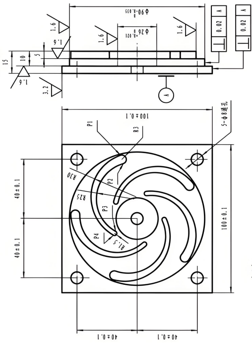
Consider a 5-axis CNC machining an impeller with a 120 mm hub diameter and 40 mm blade height. The WCS is set at the hub center (G54: X120.000, Y180.000, Z60.000). A 6 mm ball mill (TLO = 130.000 mm, CRC = 3.000 mm) finishes the blades, with the B-axis tilted 10° (Y_offset = 26.43 mm). A CMM inspection detects a 0.08 mm X-deviation, so the G54 X-offset is adjusted to 119.920 mm. Tool wear of 0.015 mm is compensated by updating TLO to 130.015 mm. The G-Code snippet is:
G54
G43 H2 Z10.0
G41 D2
G01 X0 Y26.43 Z0 F400
This ensures the toolpath aligns with the blade geometry, maintaining tolerances of ±0.015 mm.
Schlussfolgerung
Controlling coordinate offset errors in impeller machining programming demands precision in WCS setup, tool offset management, and error compensation. By following systematic procedures—such as accurate G54-G59 offsets, TLO and CRC measurements, and rotary axis calibration—programmers can achieve dimensional accuracy within tight tolerances. The outlined methods, supported by specific parameters and standardized practices, provide a robust framework for producing high-quality impellers with minimal errors.