Turbine impellers are critical components in aerospace, power generation, and marine applications, requiring exceptional precision in machining to ensure performance and reliability. Grinding, as a finishing process, plays a pivotal role in achieving the tight tolerances demanded by these components. This article provides a detailed, systematic approach to controlling grinding tolerances in turbine impeller machining, focusing on technical processes, equipment, parameters, and quality assurance methods. The content is structured to offer practical insights for engineers and manufacturers, emphasizing experience-based solutions and professional expertise.
Understanding Turbine Impeller Grinding Requirements
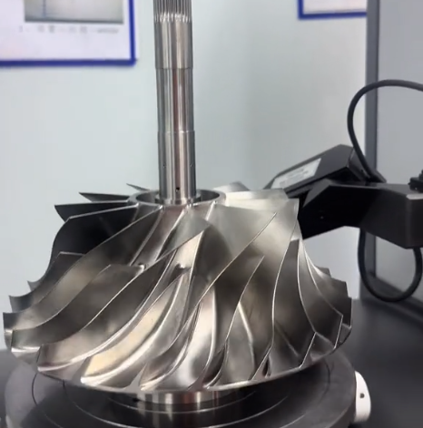
Turbine impellers feature complex geometries, including curved blades, intricate contours, and critical sealing surfaces. These characteristics necessitate precise grinding to meet dimensional and surface finish specifications, typically within tolerances of ±0.005 mm to ±0.01 mm. The primary objectives of grinding are to achieve dimensional accuracy, surface integrity, and repeatability while minimizing defects such as burns, cracks, or residual stresses.
Grinding tolerances are influenced by material properties, impeller design, and operational requirements. Common materials like Titanlegierungen (e.g., Ti-6Al-4V) and nickel-based superalloys (e.g., Inconel 718) are challenging to machine due to their high hardness and low thermal conductivity. These properties require careful selection of grinding tools, parameters, and cooling methods to maintain precision and avoid thermal damage.
Key Factors in Grinding Tolerance Control
Controlling grinding tolerances involves optimizing multiple factors, including machine setup, tooling, process parameters, and quality control. Below, each factor is explored in detail to provide a comprehensive understanding of the process.
Machine Setup and Calibration
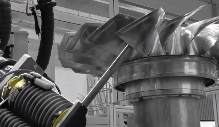
High-precision CNC grinding machines are essential for turbine impeller machining. Machines must be equipped with advanced control systems, such as Siemens Sinumerik or Fanuc CNC, to ensure accurate tool paths and repeatability. Key setup considerations include:
- Machine Stability: Ensure the machine base is vibration-free, with damping systems to absorb external disturbances. Regular maintenance of spindles and bearings is critical to prevent runout errors.
- Calibration: Calibrate machine axes using laser interferometry to achieve positioning accuracy within ±0.002 mm. Verify tool alignment with precision gauges.
- Workholding: Use custom fixtures or chucks designed for impeller geometries to minimize clamping distortion. Vacuum or magnetic chucks can enhance stability for thin-walled components.
Regular machine checks, including thermal compensation adjustments, are necessary to counteract heat-induced expansion during extended operations.
Selection of Grinding Tools
Grinding wheel selection is critical for achieving desired tolerances. Common wheel types include vitrified-bonded cubic boron nitride (CBN) and diamond wheels, which offer high wear resistance and precision for hard materials. Key parameters for wheel selection include:
| Parameter | Spezifikation | Application |
|---|---|---|
| Grit Size | 80–120 (roughing), 180–240 (finishing) | Coarse for material removal, fine for surface finish |
| Bond Type | Vitrified or resin | Vitrified for precision, resin for flexibility |
| Wheel Hardness | Medium (K–M grade) | Balances wear and cutting efficiency |
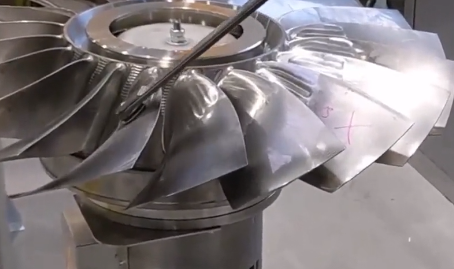
Wheel dressing is equally important. Use diamond dressers to maintain wheel geometry, with dressing intervals set based on material removal rates (typically every 50–100 passes). Automated dressing systems improve consistency and reduce operator error.
Grinding Process Parameters
Optimizing grinding parameters ensures dimensional accuracy and surface quality. Key parameters include:
- Schnittgeschwindigkeit: Typically 20–35 m/s for CBN wheels, adjusted based on material hardness. Higher speeds improve surface finish but increase heat generation.
- Vorschubgeschwindigkeit: Set at 0.01–0.05 mm/pass for finishing to minimize wheel load and thermal effects. Roughing feeds can be higher (0.1–0.2 mm/pass).
- Schnitttiefe: Limit to 0.002–0.01 mm for finishing passes to achieve tight tolerances. Multiple shallow passes are preferred over single deep cuts.
- Coolant Application: Use high-pressure coolant (10–20 bar) with water-based or oil-based fluids to reduce thermal damage. Nozzle positioning should ensure uniform cooling across the grinding zone.
Parameter optimization requires iterative testing, with adjustments based on in-process measurements and surface inspections.
Quality Control and Inspection
Robust quality control is essential to verify grinding tolerances. Inspection methods include:
- Coordinate Measuring Machines (CMM): Use touch-probe or laser-scanning CMMs to measure dimensional accuracy within ±0.001 mm. Verify critical features like blade profiles and hub diameters.
- Surface Roughness Testing: Employ profilometers to measure surface roughness (Ra 0.2–0.4 µm for finishing). Ensure compliance with aerodynamic requirements.
- Zerstörungsfreie Prüfung (NDT): Apply dye penetrant or ultrasonic testing to detect subsurface cracks or grinding burns.
In-process monitoring systems, such as acoustic emission sensors, can detect wheel wear or material anomalies in real time, enabling immediate corrective actions.
Common Issues in Grinding Tolerance Control
While the above practices enhance precision, certain issues can arise during grinding. Addressing these challenges ensures consistent results.
Thermal Damage
High temperatures during grinding can cause burns, cracks, or residual stresses, compromising impeller performance. To mitigate thermal damage:
- Use low-thermal-conductivity coolants with additives to enhance heat dissipation.
- Monitor grinding zone temperatures with infrared sensors, maintaining below 150°C for nickel alloys.
- Implement intermittent grinding cycles to allow cooling between passes.
Wheel Wear and Loading
Grinding wheels can wear unevenly or become loaded with material, reducing cutting efficiency and tolerance accuracy. Solutions include:
- Regular wheel dressing to restore cutting edges.
- Using self-sharpening CBN wheels to reduce loading.
- Adjusting feed rates to minimize wheel-material interaction time.
Clamping Distortion
Improper workholding can distort thin-walled impeller sections, leading to out-of-tolerance dimensions. To address this:
- Design fixtures with uniform clamping pressure distribution.
- Use soft jaws or compliant materials to reduce stress concentration.
- Verify fixture alignment with dial indicators before machining.
Best Practices for Consistent Tolerance Control
To achieve reliable grinding tolerances, manufacturers should adopt the following best practices:
- Process Standardization: Develop standardized operating procedures (SOPs) for machine setup, tool selection, and parameter settings. Document all process variables for traceability.
- Operator Training: Train operators on precision grinding techniques, emphasizing tool handling, parameter optimization, and quality checks.
- Data-Driven Adjustments: Use statistical process control (SPC) to monitor tolerance variations. Analyze data from CMM reports to identify trends and implement corrective actions.
- Preventive Maintenance: Schedule regular maintenance for grinding machines, including spindle balancing and coolant system cleaning, to ensure long-term accuracy.
Implementing air practices fosters a culture of precision and reliability, critical for high-stakes applications like turbine impellers.
Case Study: Parameter Optimization Example
Consider a nickel-based alloy impeller requiring a blade profile tolerance of ±0.008 mm and surface roughness of Ra 0.3 µm. Initial grinding trials using a vitrified CBN wheel (grit 120) at 25 m/s cutting speed and 0.05 mm/pass feed rate resulted in thermal burns and surface roughness of Ra 0.6 µm. Adjustments included:
- Reducing feed rate to 0.02 mm/pass.
- Increasing coolant pressure to 15 bar.
- Switching to a finer grit (180) for finishing passes.
Post-optimization, the impeller met all specifications, with no thermal damage and a surface roughness of Ra 0.25 µm. This example underscores the importance of iterative parameter tuning.
Schlussfolgerung
Controlling grinding tolerances in turbine impeller machining requires a systematic approach, integrating advanced equipment, optimized parameters, and rigorous quality control. By addressing key factors such as machine setup, tool selection, and process monitoring, manufacturers can achieve the precision demanded by high-performance applications. The methods outlined in this article, grounded in technical expertise and practical experience, provide a reliable framework for producing turbine impellers with exceptional accuracy and quality.