The impeller is a critical component in vacuum pumps, directly influencing performance metrics such as vacuum degree, pumping efficiency, and operational reliability. Achieving precise impeller profile accuracy post-machining is essential to ensure the pump operates within specified parameters. This guide provides a detailed, technical overview of the methods, tools, and processes used to control impeller profile accuracy, drawing on established manufacturing practices and precise parameters to deliver a systematic approach.
Understanding Impeller Profile Accuracy
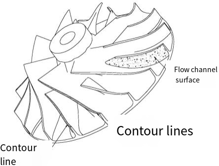
Profile accuracy refers to the degree to which the machined impeller conforms to its designed geometric specifications, including shape, dimensions, and surface finish. In vacuum pumps, the impeller's profile directly affects the clearance between the impeller and the pump housing, which is critical for maintaining vacuum integrity and minimizing energy losses. Deviations in profile accuracy can lead to reduced efficiency, increased wear, or even pump failure.
Key parameters for impeller profile accuracy include:
- Dimensional Tolerance: Typically within ±0.01 mm for high-precision vacuum pumps.
- Oberflächenrauhigkeit: Ra values often range from 0.4 to 1.6 µm, depending on the pump type.
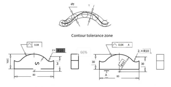
- Profile Deviation: Controlled within 0.02 mm to ensure proper fit and function.
- Blade Angle Accuracy: Deviations should be less than ±0.5° to maintain flow dynamics.
These parameters are achieved through a combination of advanced machining techniques, precise measurement, and rigorous quality control.
Machining Processes for Impeller Profile Control
The machining process is the cornerstone of achieving high impeller profile accuracy. Vacuum pump impellers, often made from materials like stainless steel, aluminum, or titanium alloys, require precise machining to meet stringent tolerances. The following methods are commonly employed:
CNC-Fräsen
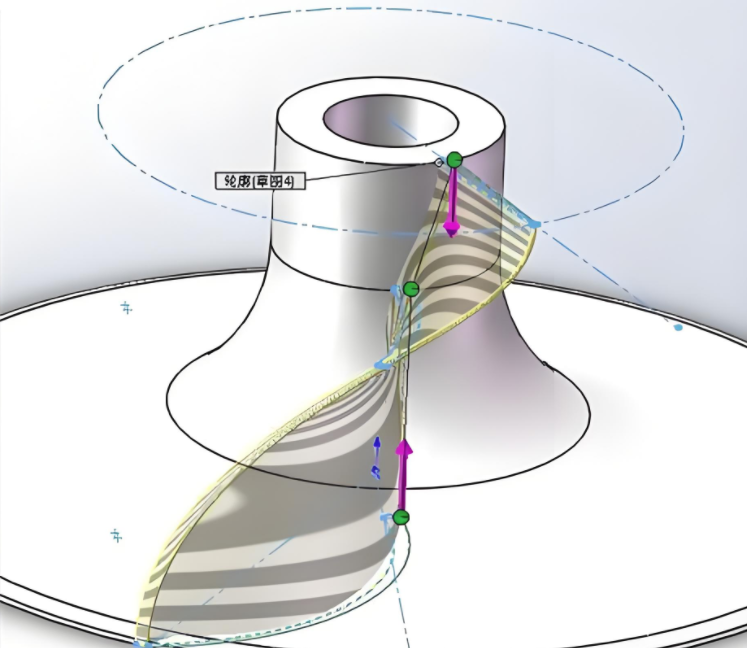
Computer Numerical Control (CNC) milling, particularly five-axis CNC milling, is widely used for impeller machining due to its ability to handle complex geometries. Five-axis machines allow for simultaneous control of multiple axes, enabling the machining of intricate blade profiles and flow channels without repositioning the workpiece. This reduces setup errors and improves profile consistency.
Key Parameters for CNC Milling:
| Parameter | Typical Value | Purpose |
|---|---|---|
| Spindeldrehzahl | 10.000-20.000 U/MIN | Ensures smooth cutting and minimizes tool vibration. |
| Vorschubgeschwindigkeit | 0.05–0.2 mm/tooth | Balances material removal rate with surface quality. |
| Werkzeug-Durchmesser | 3–10 mm | Smaller tools for narrow flow channels; larger for roughing. |
| Schnitttiefe | 0.1–0.5 mm | Prevents tool deflection and maintains precision. |
Process Considerations: Tool path optimization is critical to avoid interference between the tool and impeller blades. CAM software, such as Siemens NX or Mastercam, is used to generate precise tool paths based on the impeller’s CAD model. Additionally, high-speed machining techniques reduce thermal deformation, which can affect profile accuracy.
Turning and Grinding
For impellers requiring high surface finish, CNC turning is used for initial shaping, followed by precision grinding to achieve the desired surface roughness. Grinding is particularly important for impellers with tight tolerances, as it removes micro-imperfections left by milling.
Key Parameters for Grinding:
- Wheel Grit Size: 120–180 for finishing, ensuring Ra 0.4–0.8 µm.
- Grinding Speed: 20–30 m/s to minimize heat generation.
- Coolant Flow: Adequate to prevent thermal distortion.
Process Considerations: Grinding requires careful fixture design to ensure the impeller is securely held without introducing stress that could alter its profile. Coordinate Measuring Machines (CMMs) are often used post-grinding to verify dimensional accuracy.
Material Selection and Its Impact on Profile Accuracy
The choice of impeller material significantly affects machining outcomes. Common materials include:
- Rostfreier Stahl (z. B. 316L): Offers corrosion resistance but is prone to work hardening, requiring lower cutting speeds.
- Aluminum Alloys (e.g., 6061-T6): Easier to machine but susceptible to deformation under high cutting forces.
- Titan-Legierungen (z. B. Ti-6Al-4V): High strength-to-weight ratio but challenging to machine due to low thermal conductivity.
Material-Specific Machining Adjustments:
- For stainless steel, use coated carbide tools with a cutting speed of 50–80 m/min to reduce tool wear.
- For aluminum, increase cutting speeds to 150–200 m/min to achieve a smoother finish.
- For titanium, employ low feed rates (0.03–0.1 mm/tooth) and high-pressure coolant to manage heat.
Material properties like hardness and thermal expansion must be considered when setting machining parameters to prevent profile deviations caused by thermal or mechanical stress.
Quality Control and Measurement Techniques
Ensuring impeller profile accuracy requires robust quality control processes. The following techniques are commonly used to verify profile accuracy:
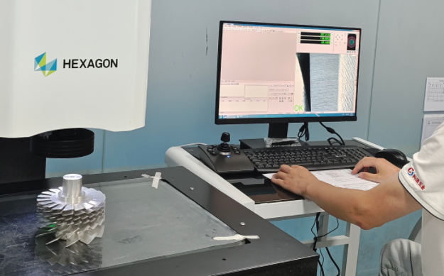
Coordinate Measuring Machines (CMMs)
CMMs provide high-precision measurements of impeller geometry by probing multiple points on the surface. They are capable of detecting deviations as small as 0.001 mm, making them ideal for verifying dimensional tolerances and profile accuracy.
CMM Measurement Parameters:
| Parameter | Typical Value | Purpose |
|---|---|---|
| Probe Diameter | 1–3 mm | Ensures access to narrow flow channels. |
| Scanning Speed | 2–5 mm/s | Balances accuracy with measurement time. |
| Point Density | 10–20 points/cm² | Captures detailed surface profiles. |
Process Considerations: CMM measurements should be conducted in a temperature-controlled environment (20 ± 1°C) to avoid thermal expansion errors. Calibration of the CMM probe is essential to ensure measurement reliability.
Optical and Laser Scanning
Non-contact methods like optical and laser scanning are increasingly used for complex impeller geometries. These systems capture thousands of data points per second, creating a digital model of the impeller for comparison with the CAD design.
Vorteile: Non-contact methods eliminate the risk of probe-induced surface damage and are faster for large surfaces.
Beschränkungen: They may have lower resolution in tight spaces, requiring hybrid approaches with CMMs for critical areas.
Post-Machining Treatments
Post-machining treatments are often necessary to refine impeller profile accuracy and enhance durability. Common treatments include:
Surface Polishing: Reduces surface roughness to Ra 0.4–0.8 µm, improving flow efficiency and reducing friction losses. Polishing is typically performed with abrasive pads or chemical polishing for hard-to-reach areas.
Wärmebehandlung: For materials like stainless steel or titanium, stress-relief annealing at 300–600°C can prevent residual stresses from causing profile distortion.
Balancing: Dynamic balancing ensures the impeller rotates without vibration, which could otherwise lead to profile wear. Balancing is performed at speeds matching the pump’s operational range (e.g., 3,000–10,000 RPM).
Practical Tips for Maintaining Profile Accuracy
Based on industry experience, the following practices enhance impeller profile accuracy:
- Tool Maintenance: Regularly inspect and replace worn tools to prevent surface imperfections.
- Fixture Design: Use custom fixtures to minimize vibration and ensure consistent clamping pressure.
- Process Monitoring: Implement real-time monitoring systems to detect deviations during machining.
- Operator Training: Ensure operators are trained in CNC programming and quality control techniques.
These practices, combined with präzise Bearbeitung and measurement, ensure that impeller profile accuracy meets design specifications.
Case Study: Vacuum Pump Impeller Manufacturing
A vacuum pump manufacturer machining a stainless steel impeller (diameter 150 mm, blade thickness 2 mm) aimed for a profile tolerance of ±0.015 mm. Using a five-axis CNC milling machine with a spindle speed of 15,000 RPM and a feed rate of 0.1 mm/tooth, the initial machining achieved a profile deviation of 0.025 mm. By optimizing the tool path with CAM software and implementing post-machining grinding (Ra 0.6 µm), the deviation was reduced to 0.012 mm. CMM verification confirmed the impeller met all specifications, demonstrating the effectiveness of combining advanced machining with rigorous quality control.
Schlussfolgerung
Controlling impeller profile accuracy in vacuum pump manufacturing requires a systematic approach involving advanced machining techniques, precise material selection, and robust quality control. By adhering to specific parameters for CNC milling, grinding, and measurement, manufacturers can achieve the tight tolerances necessary for optimal pump performance. Practical experience and attention to detail in tool maintenance, fixture design, and process monitoring further enhance outcomes. This guide provides a comprehensive framework for achieving high impeller profile accuracy, ensuring reliability and efficiency in vacuum pump operation.