Turbine impellers are critical components in industries such as aerospace, power generation, and automotive, requiring exceptional precision due to their complex geometries and demanding operational conditions. Mikron 5-axis CNC machining centers, renowned for their advanced capabilities, are widely used to manufacture these components. Achieving and maintaining precision in this process involves a combination of sophisticated equipment, optimized programming, and rigorous process control. This guide provides a detailed, technical overview of how to control precision in Mikron 5-axis machining for turbine impellers, emphasizing practical methods, specific parameters, and systematic approaches to ensure high-quality outcomes.
Understanding Turbine Impeller Geometry and Machining Requirements
Turbine impellers feature intricate, twisted blade structures, narrow flow channels, and thin-walled sections, presenting significant machining challenges. These components often require tolerances within ±0.01 mm for critical features like blade profiles and hub surfaces. Materials such as titanium alloys (e.g., Ti-6Al-4V), stainless steel, or nickel-based superalloys (e.g., Inconel 718) are commonly used, which are difficult to machine due to their high hardness, low thermal conductivity, and tendency to work-harden.
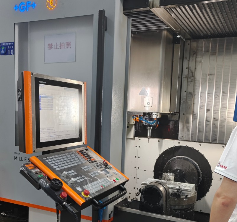
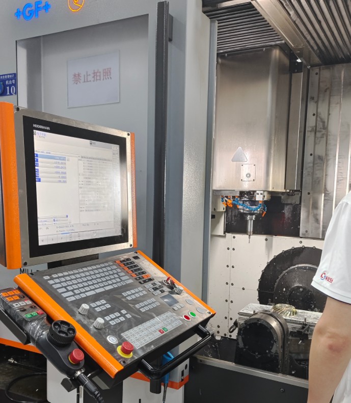
Mikron 5-Achsen-Bearbeitung centers, such as the Mikron MILL S/X or U series, are designed for high-speed, high-precision operations. These machines leverage simultaneous 5-axis motion (X, Y, Z, A, and B or C axes) to access complex surfaces in a single setup, minimizing repositioning errors and enhancing accuracy. Precision control starts with a thorough understanding of the impeller’s geometry, material properties, and the machine’s capabilities to align machining strategies effectively.
Machine Setup and Calibration
Precision machining begins with meticulous machine setup and calibration. Mikron 5-axis machining centers require regular maintenance to ensure optimal performance. Key setup and calibration steps include:
- Axis Alignment: Use laser interferometry or ballbar testing to verify the alignment of linear (X, Y, Z) and rotary (A, B/C) axes. Misalignment can cause positional errors, with deviations as small as 0.005 mm impacting surface accuracy.
- Spindle Runout Measurement: Check spindle runout with a dial indicator, ensuring it remains within 0.002 mm. Excessive runout introduces vibrations, degrading surface finish and dimensional accuracy.
- Thermal Compensation: Mikron machines often feature thermal compensation systems to counteract temperature-induced expansion. Calibrate these systems to maintain dimensional stability during extended machining cycles, targeting a thermal drift of less than 0.003 mm.
- Workpiece Fixturing: Employ high-precision fixtures, such as hydraulic or vacuum chucks, to secure the impeller blank. Limit clamping forces to 500 N to prevent deformation of thin-walled blades, which may have wall thicknesses as low as 0.5 mm.
Calibration should be conducted monthly or after significant machine downtime. Maintain detailed logs of calibration data to monitor machine performance trends and ensure consistent precision.
Tool Selection and Optimization
Selecting and optimizing cutting tools is critical for achieving precision in impeller machining. The following parameters guide tool selection:
| Parameter | Recommended Specification | Purpose |
|---|---|---|
| Werkzeug Material | Carbide or PCD (Polycrystalline Diamond) | Ensures wear resistance for hard materials like titanium or superalloys |
| Werkzeug-Durchmesser | 6–12 mm (roughing), 2–6 mm (finishing) | Balances material removal rate and precision |
| Coating | TiAlN or AlCrN | Reduces friction and heat buildup during cutting |
| Flöte zählen | 4–6 (roughing), 2–4 (finishing) | Optimizes chip evacuation and surface finish |
Tool paths should be generated using advanced CAM software like HyperMILL or SurfMill, which support complex 5-axis strategies. Key tool path strategies include:
- Roughing: Utilize trochoidal milling to minimize tool load and heat generation. Set cutting speeds at 80–120 m/min for titanium alloys and feed rates at 0.05–0.1 mm/tooth to achieve efficient material removal.
- Finishing: Apply constant scallop height tool paths to ensure a uniform surface finish, with a stepover of 0.1–0.3 mm and cutting speeds of 150–200 m/min.
- Tool Inspection: Use a tool presetter to inspect tools for wear before each machining cycle. Replace tools when edge wear exceeds 0.05 mm to maintain precision.
Proper tool management reduces chatter and deflection, ensuring consistent machining accuracy across the impeller’s complex surfaces.
CAM Programming and Tool Path Optimization
Effective CAM programming is essential for precision in 5-axis impeller machining. Software like HyperMILL, PowerMILL, or JDSoft SurfMill enables detailed tool path planning tailored to impeller geometries. Key programming techniques include:
- Collision Avoidance: Employ simulation tools like VERICUT to detect potential collisions between the tool, fixture, and workpiece. Maintain a minimum clearance of 0.5 mm to prevent damage.
- Multi-Axis Strategies: Use simultaneous 5-axis machining for blade surfaces and flow channels. Implement swivel cycle strategies to maintain continuous tool contact and avoid abrupt directional changes, reducing tool marks.
- Adaptive Feed Rates: Program variable feed rates based on material engagement. For instance, reduce feed rates by 20% in narrow flow channels (width < 3 mm) to minimize tool deflection.
- Post-Processing: Use a Mikron-compatible post-processor to translate CAM data accurately into machine code. Verify G-code using simulation software to eliminate syntax errors and ensure smooth execution.
Tool path optimization should minimize tool deflection, which can be estimated using the formula: Deflection = (F * L^3) / (3 * E * I), where F is the cutting force, L is the tool overhang length, E is the material’s modulus of elasticity, and I is the moment of inertia. Limiting tool overhang to less than 4 times the tool diameter significantly reduces deflection, enhancing precision.
Machining Process Parameters
Controlling machining parameters is vital for maintaining dimensional accuracy and surface quality. Recommended parameters for Mikron 5-axis machining of turbine impellers are outlined below:
| Operation | Material | Schnittgeschwindigkeit (m/min) | Feed Rate (mm/tooth) | Schnitttiefe (mm) |
|---|---|---|---|---|
| Aufrauen | Titan-Legierung | 80–120 | 0.05–0.1 | 0.5–2.0 |
| Fertigstellung | Titan-Legierung | 150–200 | 0.02–0.05 | 0.1–0.3 |
| Aufrauen | Nickel-Based Superalloy | 50–80 | 0.03–0.08 | 0.3–1.5 |
| Fertigstellung | Nickel-Based Superalloy | 100–150 | 0.015–0.04 | 0.05–0.2 |
Additional considerations include:
- Coolant Application: Use high-pressure coolant (70–100 bar) to improve chip evacuation and reduce thermal stress. For titanium, flood coolant with a 5–8% emulsion concentration is effective.
- Vibration Monitoring: Equip the machine with vibration sensors to detect excessive chatter. Maintain vibration levels below 2 mm/s RMS to prevent surface defects.
- In-Process Inspection: Use on-machine probing systems, such as Renishaw OMP60, to measure critical features during machining. Set probing accuracy to ±0.002 mm to verify tolerances.
These parameters should be adjusted based on real-time feedback from the machining process to optimize precision.
Quality Control and Inspection
Ensuring precision requires robust quality control and inspection processes. After machining, turbine impellers should undergo the following inspections:
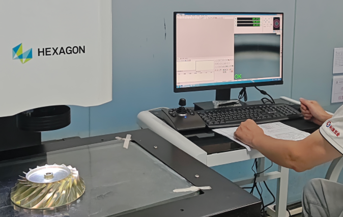
- Coordinate Measuring Machine (CMM): Use a CMM with a scanning probe to measure blade profiles and flow channels. Set measurement accuracy to ±0.005 mm and compare results against CAD models.
- Surface Roughness Testing: Measure surface roughness using a profilometer, targeting Ra values of 0.4–0.8 µm for blade surfaces to meet aerodynamic requirements.
- Zerstörungsfreie Prüfung (NDT): Perform ultrasonic or X-ray inspections to detect internal defects, such as voids or cracks, in critical areas like blade roots.
- Data Logging: Record inspection data in a quality management system to ensure traceability and compliance with standards like ISO 9001 or AS9100.
Implement statistical process control (SPC) to monitor machining consistency. Use control charts to track key dimensions, setting control limits at ±3 sigma to identify deviations early.
Common Issues and Solutions
While not all machining processes encounter significant obstacles, certain issues may arise during Mikron 5-axis machining of turbine impellers. Addressing these systematically enhances precision:
- Tool Deflection: Caused by excessive tool overhang or high cutting forces. Reduce overhang to 3–4 times the tool diameter and lower feed rates by 10–15% in high-load areas.
- Surface Imperfections: Result from tool wear or chatter. Inspect tools regularly and use vibration-dampening toolholders to minimize chatter.
- Thermal Deformation: Occurs due to heat buildup in difficult-to-machine materials. Increase coolant pressure and reduce cutting speeds by 10% to control heat generation.
Proactive monitoring and parameter adjustments can mitigate these issues, ensuring consistent precision throughout the machining process.
Schlussfolgerung
Controlling precision in Mikron 5-axis machining for turbine impellers requires a systematic approach encompassing machine setup, tool selection, CAM programming, process parameter optimization, and rigorous quality control. By adhering to the detailed parameters and best practices outlined in this guide, manufacturers can achieve tolerances within ±0.01 mm, ensuring high-quality impellers that meet stringent industry standards. Consistent calibration, optimized tool paths, and real-time process monitoring are critical to success, providing a reliable framework for precision machining excellence.