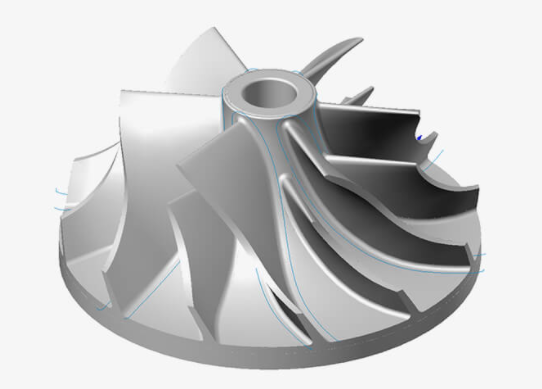
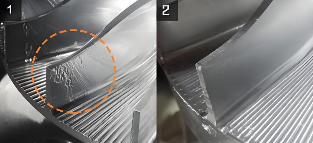
Micro-arc oxidation (MAO), also known as plasma electrolytic oxidation, is a surface treatment widely used to enhance the wear resistance, corrosion resistance, and thermal stability of high-temperature alloy impellers. These components, often made from nickel-based or titanium-based alloys, are critical in applications such as aerospace, gas turbines, and turbochargers. However, MAO inherently produces a rough surface due to the formation of micro-pores, craters, and oxide nodules, which can impact impeller performance by increasing friction, reducing aerodynamic efficiency, or compromising coating adhesion. Controlling surface roughness, typically measured as Ra (arithmetic average roughness) or Rz (maximum height of the profile), is essential to meet stringent performance requirements. This guide provides a detailed, technical approach to controlling surface roughness post-MAO, focusing on practical methods, specific parameters, and systematic processes to achieve Ra values in the optimal range of 0.5–2.0 µm.
Understanding Micro-Arc Oxidation and Surface Roughness
MAO involves applying high-voltage discharges in an electrolyte solution to form a ceramic-like oxide layer on metal surfaces. For high-temperature alloy impellers, this process creates a hard, porous coating that enhances durability but results in a rough surface due to the nature of the discharge process. Surface roughness is influenced by electrolyte composition, electrical parameters, processing time, and post-treatment methods. The goal is to balance coating thickness, hardness, and roughness to ensure functional performance. For impellers, excessive roughness (Ra > 2.5 µm) can lead to increased drag and wear, while insufficient roughness (Ra < 0.5 µm) may reduce coating adhesion. The following sections outline key factors and methods for achieving precise control over surface roughness.

Key Factors Influencing Surface Roughness in MAO
Several parameters during the MAO process directly affect the surface roughness of high-temperature alloy impellers. Optimizing these factors ensures consistent and repeatable results tailored to specific application requirements.
Electrolyte Composition
The electrolyte solution determines the morphology and roughness of the MAO coating. Common electrolytes for high-temperature alloys include alkaline solutions with sodium silicate (Na₂SiO₃), sodium phosphate (Na₃PO₄), or potassium hydroxide (KOH). The concentration and type of electrolyte influence discharge intensity and coating growth rate. For example, high silicate concentrations (15–20 g/L) produce thicker coatings with larger pores, resulting in Ra values of 2.5–3.5 µm. Phosphate-based electrolytes (5–15 g/L) promote finer discharges, yielding smoother surfaces with Ra values of 0.8–1.5 µm.
A balanced electrolyte composition, such as 10 g/L Na₂SiO₃ and 5 g/L Na₃PO₄ with a pH of 10–12, is effective for controlling roughness. Adding 1–3 g/L sodium aluminate can stabilize discharges, reducing pore size and achieving Ra values as low as 0.5 µm. The table below summarizes typical electrolyte compositions and their impact on roughness.
| Electrolyte Component | Concentration (g/L) | pH | Ra Range (µm) |
|---|---|---|---|
| Na₂SiO₃ | 10–20 | 10–12 | 2.0–3.5 |
| Na₃PO₄ | 5–15 | 10–12 | 0.8–1.5 |
| Na₂SiO₃ + Na₃PO₄ + Sodium Aluminate | 10 + 5 + 1–3 | 10–12 | 0.5–1.2 |
Electrical Parameters
Electrical parameters, including voltage, current density, pulse frequency, and duty cycle, govern the energy of micro-arc discharges and thus surface roughness. MAO for high-temperature alloys typically operates at voltages of 400–600 V and current densities of 5–20 A/dm². Higher voltages (550–600 V) increase discharge energy, forming larger craters and raising Ra to 2.0–3.0 µm. Lower voltages (400–450 V) produce finer discharges, resulting in Ra values of 0.6–1.2 µm.
Pulse frequency also plays a role. Frequencies of 500–1000 Hz ensure uniform discharge distribution, reducing roughness by preventing localized overheating. Duty cycles of 10–20% limit discharge duration, further enhancing surface uniformity. For example, a setup with 450 V, 10 A/dm², 800 Hz, and 15% duty cycle can achieve Ra values of 0.8–1.0 µm. The table below outlines electrical parameters and their effects.
| Parameter | Range | Effect on Ra (µm) |
|---|---|---|
| Voltage | 400–450 V | 0.6–1.2 |
| Voltage | 550–600 V | 2.0–3.0 |
| Pulse Frequency | 500–1000 Hz | 0.8–1.5 |
| Duty Cycle | 10-20% | 0.8–1.2 |
Processing Time
The duration of the MAO process affects coating thickness and roughness. Longer processing times (20–30 minutes) increase coating thickness to 50–100 µm, with larger pores and higher Ra values (2.0–3.5 µm). Shorter times (5–15 minutes) produce thinner coatings (10–30 µm) with smaller pores and lower Ra values (0.5–1.5 µm). For impellers, a processing time of 10–15 minutes is typically optimal to balance coating durability and smoothness.
Monitoring the coating growth rate is critical, as roughness increases non-linearly with time due to intensified discharges. Regular inspection using profilometers during process optimization helps maintain Ra within the desired range.
Post-Treatment Methods for Surface Roughness Control
While optimizing MAO parameters reduces initial roughness, post-treatment methods are often necessary to achieve the target Ra for high-temperature alloy impellers. These methods refine the surface without compromising coating integrity.
Mechanical Polishing
Mechanical polishing, such as abrasive blasting or grinding, smooths the MAO coating by removing surface protrusions. Using fine abrasives like aluminum oxide (Al₂O₃) with a grit size of 800–1200, followed by polishing with diamond paste (1–3 µm), can reduce Ra from 2.5 µm to 0.5–0.8 µm. Care must be taken to avoid excessive material removal, which can thin the coating below the critical thickness (10–20 µm) required for durability.
Polishing pressure should be controlled at 0.1–0.2 MPa, with a processing time of 5–10 minutes per impeller section. Automated polishing systems ensure uniformity, especially for complex impeller geometries.
Chemical Etching
Chemical etching selectively removes surface irregularities using mild acidic solutions, such as 5–10% hydrofluoric acid (HF) or 10% nitric acid (HNO₃), applied for 30–60 seconds. This method reduces Ra by 0.5–1.0 µm while preserving coating porosity, which is essential for thermal barrier properties. Etching must be followed by thorough rinsing to prevent residual acid from affecting the impeller’s performance.
Etching is particularly effective for titanium-based alloys, where MAO coatings are highly porous. However, it requires precise control to avoid over-etching, which can weaken the coating’s adhesion.
Sealing Treatments
Sealing fills surface pores with materials like silica (SiO₂) or organic polymers, reducing roughness and improving corrosion resistance. A common sealing solution contains 5–10 g/L sodium silicate applied at 80–90°C for 10–20 minutes. This method can lower Ra from 1.5 µm to 0.8–1.0 µm while enhancing surface uniformity.
Sealing is less aggressive than polishing or etching, making it suitable for impellers requiring minimal surface alteration. However, it may slightly reduce coating hardness, so it should be evaluated based on application requirements.

Practical Considerations for Implementation
Implementing roughness control methods requires a systematic approach to ensure repeatability and quality. Key considerations include:
- Process Monitoring: Use real-time monitoring tools like profilometers and scanning electron microscopes (SEM) to assess roughness and coating morphology during MAO and post-treatment.
- Parameter Optimization: Conduct factorial experiments to identify the optimal combination of electrolyte, electrical parameters, and processing time for specific alloy compositions.
- Equipment Calibration: Regularly calibrate MAO power supplies and polishing equipment to maintain consistent discharge energy and surface finish.
- Qualitätskontrolle: Establish quality control protocols, including Ra and Rz measurements at multiple impeller locations, to verify compliance with specifications.
These steps ensure that the MAO process and post-treatments are tailored to the impeller’s material and application, minimizing variability and enhancing performance.
Schlussfolgerung
Controlling surface roughness of high-temperature alloy impellers after micro-arc oxidation is a complex but achievable task through careful optimization of MAO parameters and post-treatment methods. By adjusting electrolyte composition, electrical parameters, and processing time, and applying techniques like mechanical polishing, chemical etching, or sealing, manufacturers can achieve Ra values of 0.5–2.0 µm, meeting the demands of high-performance applications. A systematic approach, supported by precise monitoring and quality control, ensures consistent results. This guide provides the technical foundation for engineers and technicians to implement effective roughness control strategies, enhancing the durability and efficiency of MAO-treated impellers.
