Concentricity error in a turbomolecular pump impeller is a critical factor affecting the pump's performance, efficiency, and longevity. Turbomolecular pumps operate at extremely high speeds, often between 20,000 and 90,000 rpm, to create high vacuum environments. Any misalignment or deviation in the impeller's concentricity can lead to imbalance, increased wear, vibration, and potential failure of the pump system. This guide provides a systematic and technical approach to measuring concentricity error in a turbomolecular pump impeller, detailing tools, procedures, and key considerations for achieving precise measurements.
Understanding Concentricity in Turbomolecular Pump Impellers
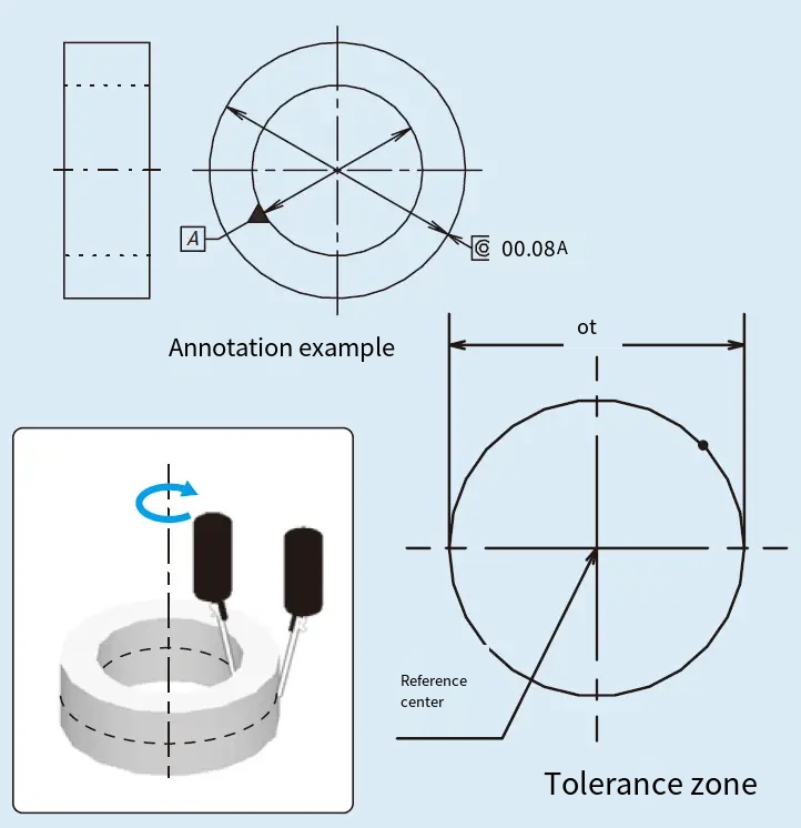
Concentricity refers to the alignment of the impeller’s rotational axis with its geometric center. In turbomolecular pumps, the impeller consists of a series of rotor blades arranged in multiple stages, paired with stationary stator blades, to compress gas molecules and maintain a vacuum. The impeller is typically mounted on a shaft, and any deviation from perfect concentricity can cause uneven forces during high-speed rotation, impacting the pump’s ability to achieve pressures as low as 10⁻⁸ Pa. Concentricity error is quantified as the deviation of the impeller’s rotational axis from its ideal centerline, typically measured in micrometers (µm).
Accurate measurement of concentricity error is essential for quality control during manufacturing, assembly, and maintenance. The impeller’s high rotational speeds amplify even minor misalignments, making precision critical. The measurement process involves assessing the impeller’s hub, shaft, and bore alignment under both no-load and operational conditions.
Tools Required for Measuring Concentricity Error
Measuring concentricity error requires specialized tools to ensure high precision, given the tight tolerances in turbomolecular pump impellers. Below is a table listing the essential tools and their specifications:
| Tool | Beschreibung | Specifications |
|---|---|---|
| Dial Indicator | Measures radial runout by contacting the impeller or shaft surface. | Resolution: 0.001 mm; Range: 0-1 mm |
| Feeler Gauge | Measures clearance between impeller and casing or bore. | Thickness range: 0.01-1 mm |
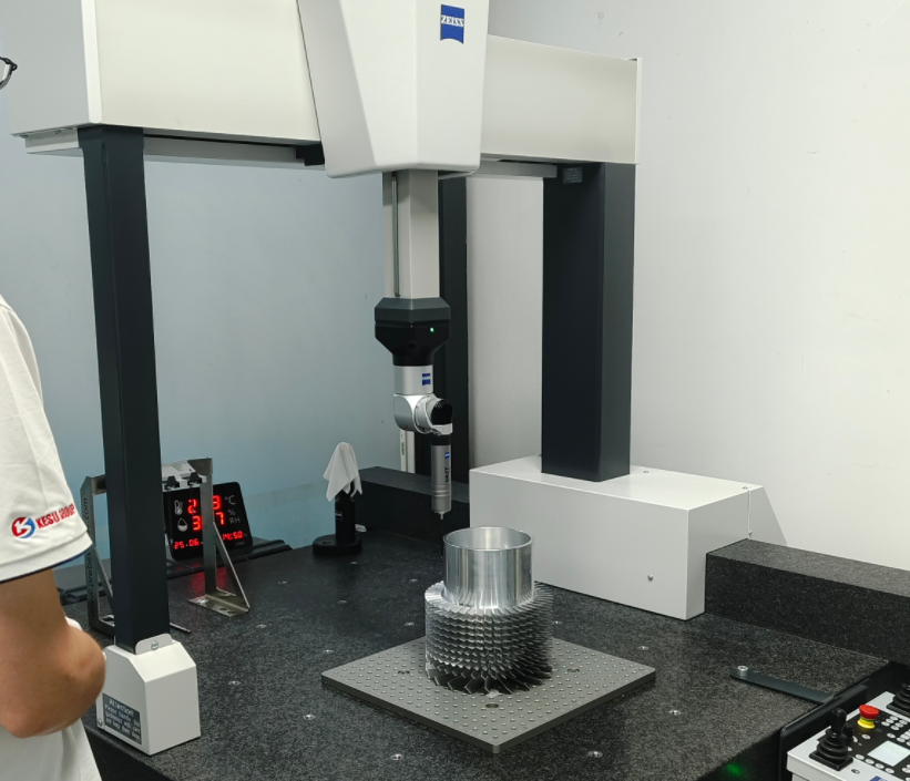
| Koordinatenmessmaschine (CMM) | Provides precise 3D measurements of impeller geometry. | Accuracy: ±0.002 mm |
| V-Block Supports | Supports the shaft during no-load measurements. | Material: Hardened steel; Flatness: 0.01 mm |
| Laser Alignment System | Non-contact measurement of shaft and impeller alignment. | Resolution: 0.001 mm; Range: 0-10 mm |
Additional tools, such as precision calipers (0.01 mm resolution) and micrometers (0.001 mm accuracy), may be used for supplementary measurements. The choice of tools depends on the impeller’s design, the required precision, and whether measurements are conducted in a lab or during assembly.
Measurement Procedure
The process of measuring concentricity error in a turbomolecular pump impeller involves several steps, performed under controlled conditions to ensure accuracy. The procedure is divided into preparation, no-load measurement, and operational condition measurement.
Preparation
Before measurement, ensure the impeller and shaft are clean and free of debris, as contaminants can affect results. Verify that the measurement environment is stable, with a temperature range of 20-25°C and relative humidity below 60% to prevent thermal expansion or condensation on precision surfaces. Disassemble the pump to access the impeller, following the manufacturer’s guidelines to avoid damaging delicate components. Secure the impeller and shaft in a stable setup, such as V-block supports, for no-load measurements.
No-Load Measurement
Under no-load conditions, the impeller is not subjected to operational forces, allowing for baseline measurements of concentricity. Follow these steps:
- Setup: Place the shaft on V-block supports, ensuring it is level and stable. If the impeller is part of a subassembly, use a temporary bushing to replace support bearings, as described in some water pump concentricity protocols, which can be adapted for turbomolecular pumps.
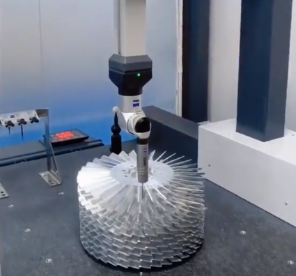
- Dial Indicator Measurement: Mount a dial indicator on a fixed stand, positioning the probe against the impeller’s hub or shaft surface. Rotate the shaft manually at a slow, consistent speed (e.g., 10 rpm) and record the maximum and minimum readings. The total indicator runout (TIR) represents the concentricity error, typically acceptable within 0.05 mm for high-precision impellers.
- Feeler Gauge Check: Insert feeler gauges into the clearance between the impeller hub and bore at multiple points (e.g., 0°, 90°, 180°, 270°). Record variations in clearance, which indicate misalignment. Allowable clearance is typically 0.01-0.05 mm, depending on the pump’s specifications.
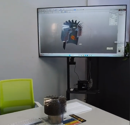
- CMM Verification: Für higher accuracy, use a CMM to map the impeller’s geometry. Measure the coordinates of the hub, bore, and shaft at multiple points to calculate the centerline deviation. The CMM can detect errors as small as 0.002 mm.
Record all measurements systematically, noting the positions and deviations. If the concentricity error exceeds the allowable limit (e.g., 0.05 mm), inspect components such as the shaft shoulder, impeller hub, or balance drum for defects.
Operational Condition Measurement
Operational conditions introduce dynamic forces that can affect concentricity, such as thermal expansion or shaft deflection. To measure concentricity under load:
- Reassemble the Pump: Reinstall the impeller and shaft into the pump housing, ensuring proper alignment as per manufacturer guidelines. Tighten locknuts to secure the rotor, but avoid over-torquing, which can introduce stress.
- Laser Alignment System: Use a laser alignment system for non-contact measurement. Mount the laser emitter on the shaft and the receiver on the pump casing. Rotate the shaft at a low speed (e.g., 100-200 rpm) to simulate operational conditions without reaching full speed (20,000-90,000 rpm). Record the misalignment data, which typically should not exceed 0.01 mm for critical components.
- Dynamic Runout Measurement: Use a dial indicator to measure runout during low-speed rotation. Compare these results with no-load measurements to identify dynamic effects. If the runout exceeds 0.01 mm, further inspection of the shaft or bearings is required.
- Verification: Recheck concentricity after adjustments, such as adding shims or re-machining the impeller hub, to ensure compliance with tolerances.
Operational measurements are critical for turbomolecular pumps, as high-speed rotation amplifies small errors. Ensure the pump is not operated at full speed during measurement to avoid damage.
Key Considerations for Accurate Measurement
Several factors must be addressed to ensure accurate concentricity measurements:
- Tool Calibration: Calibrate all measurement tools before use. For example, dial indicators should be zeroed on a reference surface, and CMMs should be calibrated to a standard within ±0.001 mm.
- Environmental Control: Maintain stable temperature and humidity to prevent thermal expansion of the impeller or shaft, which can skew results by up to 0.01 mm per 10°C change.
- Surface Condition: Ensure the impeller and shaft surfaces are free of burrs, scratches, or corrosion, as these can affect contact-based measurements like dial indicators or feeler gauges.
- Bearing Influence: Magnetic or oil-lubricated bearings in turbomolecular pumps can introduce slight misalignments. Use temporary bushings during no-load measurements to isolate the impeller’s concentricity.
- Measurement Points: Take measurements at multiple angular positions (e.g., every 90°) to capture the full profile of the impeller and shaft. A minimum of four points is recommended.
Failure to address these considerations can lead to inaccurate measurements, resulting in improper adjustments and potential pump failure during operation.
Data Analysis and Correction
After collecting measurements, analyze the data to determine the concentricity error. Calculate the TIR by subtracting the minimum dial indicator reading from the maximum. For example, if the maximum reading is 0.03 mm and the minimum is -0.02 mm, the TIR is 0.05 mm. Compare this with the manufacturer’s tolerance, typically 0.01-0.05 mm for turbomolecular pump impellers.
If the error exceeds the tolerance, corrective actions include:
- Re-machining: Re-machine the impeller hub or shaft to reduce runout. Ensure machining does not alter the impeller’s balance, which is critical at high speeds.
- Shimming: Insert precision shims (0.01-0.1 mm thickness) between the impeller and shaft to adjust alignment.
- Replacement: If defects are severe, replace the impeller or shaft. Verify new components meet tolerances before assembly.
Document all measurements and corrections in a log, including tool used, measurement conditions, and final TIR values. This ensures traceability and aids in future maintenance.
Practical Example
Consider a turbomolecular pump impeller with a 100 mm diameter, operating at 36,000 rpm. During no-load testing, a dial indicator measures a TIR of 0.06 mm, exceeding the 0.05 mm tolerance. Using a CMM, the hub’s centerline deviation is found to be 0.03 mm. After re-machining the hub to reduce the deviation to 0.01 mm, a laser alignment system confirms the operational concentricity error is within 0.01 mm. This example demonstrates the importance of using multiple tools and iterative corrections to achieve acceptable concentricity.
Schlussfolgerung
Measuring concentricity error in a turbomolecular pump impeller requires precision tools, systematic procedures, and careful consideration of environmental and mechanical factors. By following the outlined steps—preparation, no-load and operational measurements, and data analysis—engineers can ensure the impeller meets stringent tolerances, maintaining the pump’s performance and reliability. Regular maintenance and verification of concentricity are essential to prevent operational issues in high-vacuum systems.