Impeller tolerances are critical in ensuring the performance, balance, and assembly quality of rotating components in mechanical systems. These tolerances encompass dimensional, shape, positional, surface roughness, dynamic balance, and material-related requirements. This guide provides a detailed overview of impeller tolerances, focusing on centrifugal and axial impellers used in pumps, fans, and turbines, with specific parameters and industry standards.
Dimensional Tolerances
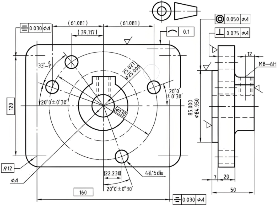
Dimensional tolerances define the allowable deviation in impeller components such as diameter, thickness, blade height, and shaft bore diameter. These tolerances ensure proper assembly and operational efficiency.
| Component | Tolerance Range (ISO IT Grades) | Typische Werte | Application Impact |
|---|---|---|---|
| Outer Diameter | IT6–IT8 | ±0.01–0.03 mm (e.g., Ø200 mm impeller) | Affects dynamic balance and clearance |
| Shaft Bore Diameter | H6–H7 | +0.012–0 mm (e.g., Ø50 mm bore) | Ensures proper shaft fit (interference/clearance) |
| Blade Thickness | IT7–IT9 | ±0.02–0.05 mm | Impacts fluid dynamics and structural integrity |
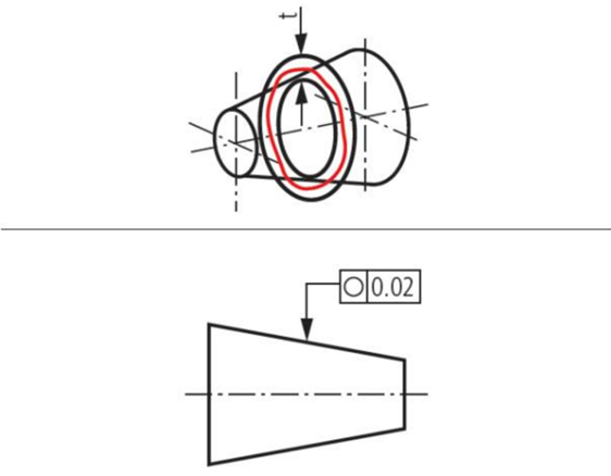
Shape Tolerances
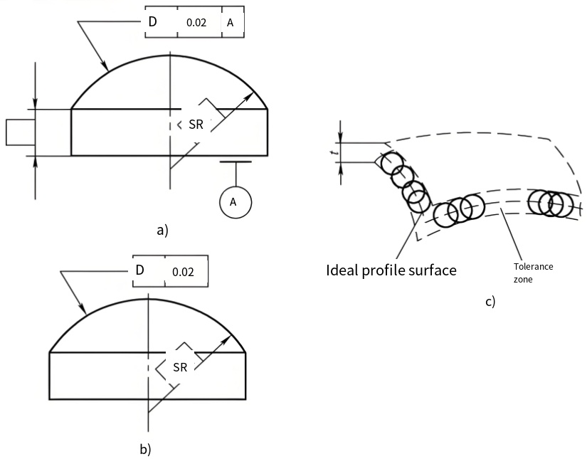
Shape tolerances control the geometric accuracy of impeller components, ensuring aerodynamic performance and rotational stability.
- Roundness: Typically 0.01–0.05 mm for outer diameter or shaft bore, critical for high-speed impellers.
- Cylindricity: 0.02–0.08 mm for shaft bore or outer diameter, ensuring uniform contact surfaces.
- Ebenheit: 0.02–0.1 mm for impeller end faces, depending on impeller size, to maintain balance.
Impact: Deviations in shape can lead to airflow disruption or imbalance, reducing efficiency and increasing wear.
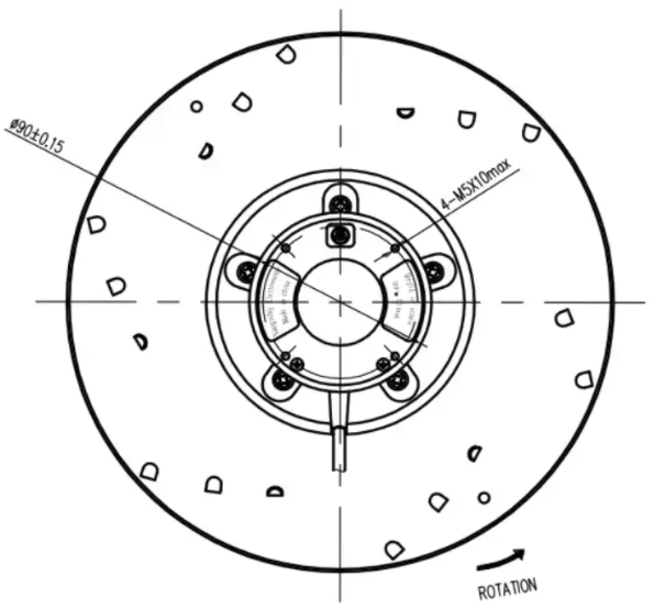
Positional Tolerances
Positional tolerances ensure accurate alignment and orientation of impeller components, such as blade angles and shaft bore concentricity.
- Konzentrationsfähigkeit: 0.01–0.05 mm for shaft bore to outer diameter, critical for rotational stability.
- Parallelität: 0.02–0.08 mm for end faces relative to the axis, ensuring uniform load distribution.
- Blade Angle Deviation: ±0.5°–2° for centrifugal impellers, ±0.2°–0.8° for axial impellers, affecting fluid flow.
Impact: Positional errors can cause misalignment, leading to vibration and reduced operational lifespan.
Oberflächenrauhigkeit

Surface roughness affects aerodynamic performance and wear resistance, measured as Ra (roughness average).
| Component | Ra Range (μm) | Application Impact |
|---|---|---|
| Blade Surface | 0.8–3.2 | Reduces airflow resistance, enhances efficiency |
| Shaft Bore Surface | 0.4–1.6 | Ensures smooth shaft fit, reduces friction |
Dynamic Balance Tolerances
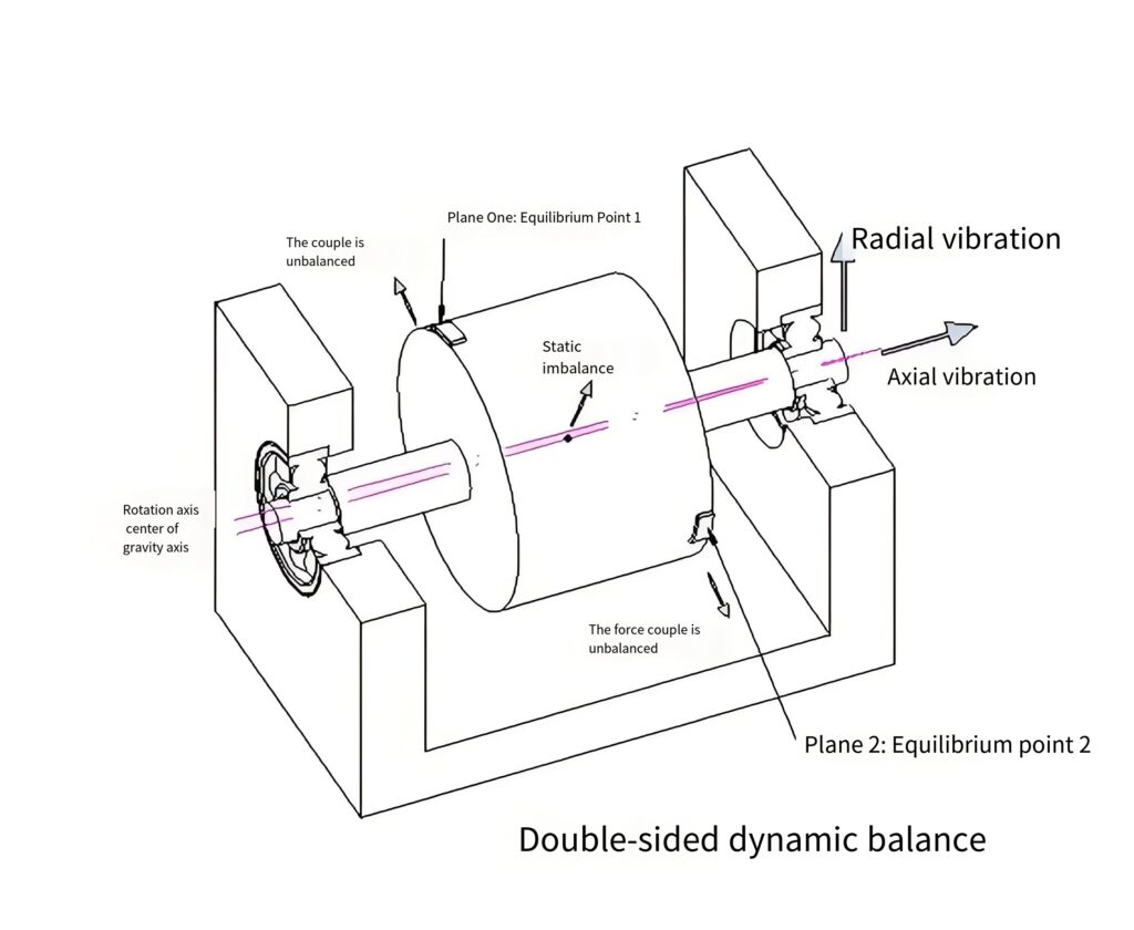
Dynamic balance is essential for minimizing vibration in rotating impellers, specified by unbalance limits (g·mm) and balance grades per ISO 1940-1.
- Balance Grades: G2.5 for high-speed impellers (e.g., turbines), G6.3 for medium-speed impellers (e.g., pumps).
- Unbalance Limit: 0.1–1 g·mm for high-speed impellers, 1–5 g·mm for industrial applications.
- Impact: Poor balance causes excessive vibration, reducing bearing life and system efficiency.
Material and Heat Treatment Tolerances
Material properties and heat treatment processes introduce tolerances related to hardness and dimensional stability.
- Härte: HRC ±2 for high-strength impellers (e.g., stainless steel or titanium alloys).
- Deformation: ±0.01–0.03 mm post-heat treatment, critical for high-precision applications.
- Impact: Material tolerances ensure durability and resistance to fatigue under operational stresses.
Application-Specific Tolerances
Tolerance requirements vary by impeller type and application, such as centrifugal or axial impellers used in pumps, fans, or turbines.
Centrifugal Impellers
Used in centrifugal pumps, fans, and turbochargers, these impellers require tight tolerances for high-speed applications.
- Pumps: IT7–IT8, G6.3 balance, Ra 1.6–3.2 μm, blade angle ±1°.
- Fans: IT8–IT9, G6.3–G16 balance, Ra 1.6–3.2 μm, less stringent due to lower speeds.
- Turbochargers: IT5–IT6, G2.5 balance, Ra 0.4–0.8 μm, blade angle ±0.5° for high-speed stability.
Axial Impellers
Used in axial fans, propellers, and turbine blades, these impellers prioritize blade angle and surface finish.
- Fans: IT8–IT9, G6.3 balance, Ra 1.6–3.2 μm, blade angle ±1°–2°.
- Propellers: IT7–IT8, G6.3 balance, Ra 0.8–1.6 μm, corrosion-resistant materials.
- Turbinenschaufeln: IT5–IT6, G2.5 balance, Ra 0.4–0.8 μm, blade angle ±0.2° for aerospace applications.
Turbomolecular Impellers
- Application: Turbomolecular pumps for high-vacuum systems (e.g., semiconductor manufacturing, mass spectrometry).
- Toleranzen:
- Dimensional Tolerance: IT4–IT5, due to ultra-high rotational speeds requiring extreme precision in blade geometry and alignment.
- Balance Quality: G1.0–G2.5 (ISO 1940-1), as even minor imbalances can cause significant vibrations at 20,000–90,000 RPM.
- Surface Finish: Ra 0.2–0.4 μm, to minimize gas turbulence and ensure efficient molecular flow in vacuum conditions.
- Blade Angle: ±0.1°–0.2°, critical for maintaining consistent pumping efficiency and molecular transfer.
- Material Considerations: Often made from lightweight, high-strength materials like aluminum alloys or titanium, with coatings to resist corrosion and wear in vacuum environments.
Industry Standards and Manufacturing Considerations
Impeller tolerances adhere to international standards and depend on manufacturing processes.
- Standards:
- ISO 2768: General tolerances for unspecified dimensions.
- ISO 8015: Principles for tolerance specification.
- ASME Y14.5: Geometric Dimensioning and Tolerancing (GD&T).
- ISO 1940-1: Dynamic balance grades.
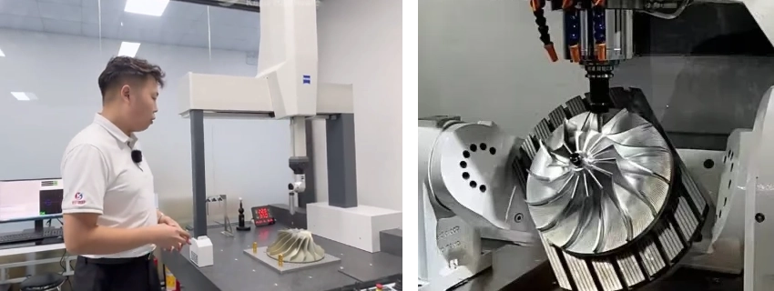
- Manufacturing Processes: CNC machining, precision casting, or additive manufacturing for high-precision impellers; tolerances tighten with advanced techniques.
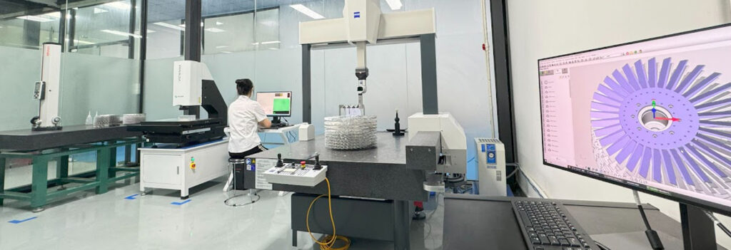
- Inspection Methods: Coordinate Measuring Machines (CMM), laser scanning, and dynamic balancing machines ensure compliance.
Schlussfolgerung
Impeller tolerances are pivotal for ensuring performance, reliability, and longevity in applications like pumps, fans, and turbines. By adhering to precise dimensional, shape, positional, surface, and balance tolerances, manufacturers can achieve optimal aerodynamic performance and mechanical stability. Application-specific requirements and industry standards, such as ISO and ASME, guide tolerance specifications, while advanced manufacturing and inspection techniques ensure compliance.