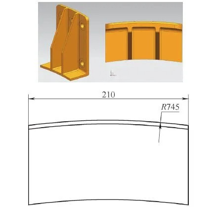
Large curved surfaces are common features in mechanical components, yet their machining poses significant technical challenges, particularly for large-scale parts. This article presents a systematic approach to machining large curved surfaces on a horizontal four-axis CNC machine. By establishing a mathematical model and developing a fully parameterized macro program, this method enhances machining efficiency and ensures high-quality outcomes. The approach is demonstrated using a specific part with dimensions 280mm × 210mm × 114mm and an outer curved surface radius of 745mm. The following sections detail the machining analysis, technical scheme, mathematical modeling, macro programming, and practical results.
Machining Analysis
Curved surfaces are prevalent in mechanical engineering, but machining large curved surfaces remains complex due to their size, geometry, and precision requirements. For the part in question, the outer curved surface has a radius of 745mm, with a length of 280mm along the arc. Traditional machining methods for such surfaces include rough and finish machining, with finish machining being particularly challenging. Two conventional approaches were initially considered:
- Circumferential Milling: Milling along the circumferential direction of the arc requires extended tool overhang, leading to tool vibration, accelerated wear, reduced tool life, poor surface quality, and low efficiency.
- Arc-Step Milling: Using a ball-end or corner-radius mill, cutting along the generatrix with small step increments to approximate the curve. Due to the large radius and stringent surface roughness requirements, this method demands very small step sizes, resulting in long machining times (approximately two hours for the part).
After evaluation, an optimized approach was selected: using a face milling cutter to machine along the generatrix of the curved surface. The workpiece is clamped such that the arc’s central axis is perpendicular to the machine table. The table rotates incrementally, and the tool cuts along the generatrix with each rotation, repeating until the surface is fully formed. The primary challenge lies in developing a robust macro program to control this process, especially when the arc’s center does not align with the machine table’s center.
Technical Scheme
The proposed method leverages the four-axis capability of the CNC machine to achieve precise and efficient machining of large curved surfaces. The technical scheme addresses the general case where the arc’s center is offset from the machine table’s center, a common scenario due to spatial constraints in clamping. The approach involves setting up a coordinate system, performing mathematical calculations for tool positioning, and executing a parameterized macro program to automate the process.
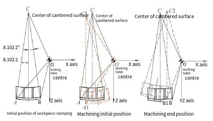
Coordinate System Setup
The coordinate system is defined with the X and Z axes’ zero point at the machine table’s center (point O) and the Y-axis zero point at the top of the curved surface. The workpiece is positioned such that the arc’s center (point C) is offset from the table’s center. The machining process involves rotating the table incrementally (e.g., 0.5° per step) and cutting along the generatrix for each rotation. The starting position (point A) and ending position (point B) of the machining path are calculated based on the arc’s geometry and the offset.
Mathematical Modeling
A mathematical model is essential to determine the tool’s position for each cut. The model accounts for the offset between the arc’s center and the table’s center, the arc’s radius, and the tool’s geometry. Key parameters include:
| Parameter | Beschreibung | Value (Example) |
|---|---|---|
| R1 | X-coordinate of arc center relative to table center | 100 mm |
| R2 | Z-coordinate of arc center relative to table center | -515 mm |
| R3 | Initial angle of rotation | -9° |
| R4 | Arc radius | 745 mm |
| R5 | Arc length | 280 mm |
| R6 | Tool radius | 25 mm |
The model calculates the angle between the line connecting the arc center to the table center and the positive Z-axis. This angle, combined with the rotation increment, determines the tool’s position in the X-Z plane for each cut. The Y-axis position is adjusted to account for the tool radius and ensure proper depth of cut. The residual height after machining is calculated to be 0.0071 mm, meeting precision requirements.
Macro Program Development
The macro program, written for a Siemens CNC system, automates the machining process. It includes parameter assignments, quadrant determination for the arc center’s position, angle calculations, and iterative machining steps. The program logic is as follows:
- Assign initial parameters (e.g., arc radius, tool radius, initial angle).
- Determine the quadrant of the arc center relative to the table center to calculate the initial angle.
- Calculate the tool’s X, Z, and Y coordinates for each rotation increment.
- Execute linear cuts along the generatrix, adjusting the Y position based on tool radius and arc length.
- Repeat until the final angle (e.g., 9°) is reached, completing the surface.
The program uses a 50 mm face milling cutter, with the table rotating 0.5° per step for 36 steps. Key commands include:
G54; Set coordinate system
G64; Enable continuous cutting mode
SOFT; Enable smooth acceleration/deceleration
FFWON; Enable feedforward control
T1D1; Select 50 mm face milling cutter
G0 X300 Y60 Z500; Move to safe position
R1=100; X-coordinate of arc center
R2=-515; Z-coordinate of arc center
R3=-9; Initial angle
R4=745; Arc radius
R5=280; Arc length
R6=25; Tool radius
R7=-1; Direction control
R11=SQRT(R1*R1+R2*R2); Rotation radius
R9=ASIN(R1/SQRT(R1*R1+R2*R2)); Angle calculation
The program includes conditional jumps to handle quadrant-specific angle calculations and loops to iterate through the 36 steps. The tool path extends slightly beyond the arc length (using a 1.2 extension factor) to ensure complete coverage.
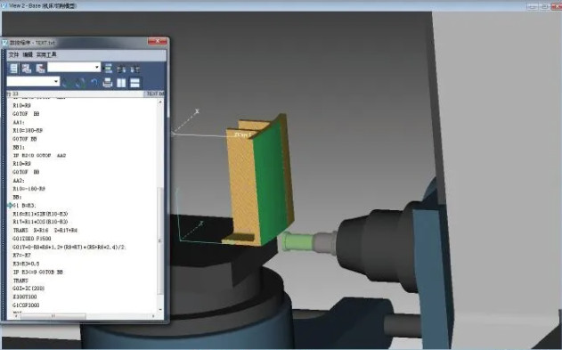
Simulation und Verifizierung
The macro program was simulated using VERICUT software to validate the tool path and machining parameters. The simulation confirmed that the tool followed the intended path, achieving a residual height of 0.0071 mm and meeting surface quality requirements. The simulation also verified the absence of collisions or overcuts, ensuring the program’s reliability for actual machining.
Practical Implementation
The method was implemented on a horizontal four-axis CNC machine with the following setup:
- Workpiece Clamping: The workpiece was clamped to align the arc’s central axis perpendicular to the table. A reference block was used to calibrate the table’s center, minimizing positional errors.
- Tool Selection: A 50 mm face milling cutter was used, with a spindle speed of 1300 RPM and a feed rate of 1500 mm/min for X-axis positioning and 2000 mm/min for Z-axis positioning.
- Machining Parameters: The table rotated 0.5° per step, with 36 steps covering the arc from -9° to 9°. The Y-axis position was adjusted to account for the tool radius and arc geometry.
The machining process was stable, with no significant vibrations or tool wear issues. The total machining time was significantly reduced compared to traditional methods, achieving an eightfold improvement in efficiency (from approximately two hours to about 15 minutes).
Results and Benefits
The proposed method offers several advantages over traditional approaches:
| Aspekt | Traditional Methods | Proposed Method |
|---|---|---|
| Bearbeitungszeit | ~2 hours | ~15 minutes |
| Surface Quality | Poor (vibration, tool wear) | High (residual height 0.0071 mm) |
| Tool Life | Short (due to vibration) | Extended (stable process) |
| Programming Complexity | Mäßig | High (but reusable macro) |
The method’s parameterized macro program is adaptable to different arc radii, lengths, and offsets, making it versatile for various curved surface geometries. The use of a face milling cutter and incremental rotation ensures stability and precision, while the mathematical model and simulation reduce the risk of errors.
Schlussfolgerung
This article presents a systematic and efficient method for machining large curved surfaces on a horizontal four-axis CNC machine. By using a face milling cutter, establishing a mathematical model, and developing a fully parameterized macro program, the method achieves significant improvements in efficiency and quality. The approach is particularly effective for cases where the arc’s center is offset from the table’s center, offering a generalizable solution for complex curved surface machining. Practical implementation and simulation results confirm the method’s reliability, making it a valuable tool for precision manufacturing.