The impeller is a critical component of marine pump assemblies, directly influencing overall performance through its dimensional accuracy, blade geometry, and machining quality. Poor machining precision can lead to assembly inaccuracies, causing significant hydraulic losses at the pump inlet and blades, potentially resulting in balance failures. This article outlines a systematic machining and inspection process for marine pump impellers, focusing on addressing the challenges of complex spatial dimension chains through dimension conversions, taper gauge design, and inspection templates. The process has been validated through practical machining and assembly, ensuring reliable dimensional accuracy and assembly performance.
Impeller Structure and Characteristics
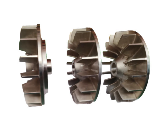
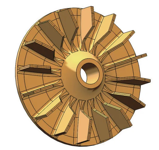
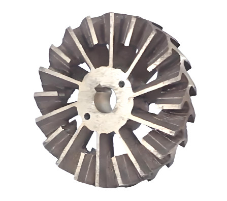
The impeller is an open-type, non-fully rotational, irregularly shaped cast copper component made of ALBC3 material. It features multiple blades arranged radially around the circumference. Each impeller undergoes static balance testing, while the complete pump assembly is subjected to dynamic balance testing to ensure operational stability.
The impeller’s central feature is a 1:50 tapered bore, with blades forming a 10° conical surface. These elements are critical to the impeller’s functionality, as they interact directly with the pump’s hydraulic performance. The complexity of the impeller’s geometry, particularly the spatial relationship between the blades and the tapered bore, poses significant challenges for impeller machining and inspection.
Dimensional Accuracy Requirements
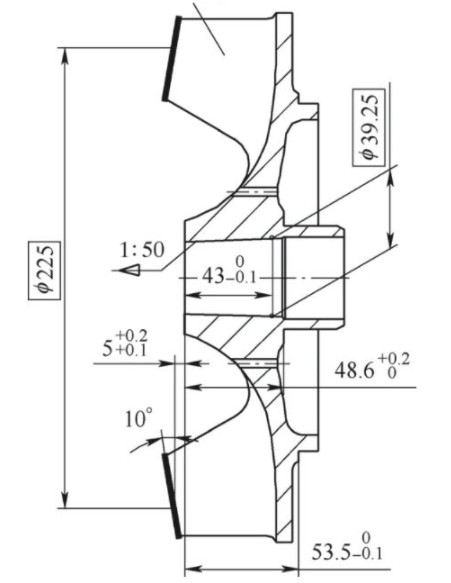
The impeller’s dimensional accuracy is paramount to its performance. The primary precision requirements include:
- Central Tapered Bore: A 1:50 taper with a diameter of φ39.25 mm.
- Blade Conical Surface: A 10° taper angle.
- Spatial Dimension Chains:
- Chain 1: φ39.25 mm, 1:50 taper, and 43 mm (0, -0.1 mm).
- Chain 2: 48.6 mm (+0.2, 0 mm), 5 mm (+0.2, +0.1 mm), φ225 mm, and 10°.
These dimensions form two complex spatial dimension chains that govern the impeller’s interaction with the pump assembly. Ensuring compliance with these tolerances is critical to avoiding interference during assembly and maintaining hydraulic efficiency.
Machining and Inspection Challenges
The impeller’s blades and central tapered bore are machined using turning operations, but they cannot be completed in a single setup due to the component’s geometry. Two separate setups are required, necessitating a headstock reversal, which complicates the machining of the blade’s spatial dimensions (φ225 mm, 5 mm (+0.2, +0.1 mm), and 10°). These dimensions cannot be directly machined or measured with standard tools due to their spatial nature and the non-continuous conical surface of the blades.
The assembly clearance ranges from 0.22 mm to 2.63 mm. The rough surface of the 10° blade conical surface, combined with the spatial and non-continuous nature of the measured elements, renders conventional measurement methods, such as coordinate measuring machines (CMMs), ineffective. This necessitates specialized inspection tools and techniques to verify the theoretical spatial dimensions.
Machining Process and Solutions
To address the challenges of machining and inspecting the impeller’s complex spatial dimension chains, a systematic process was developed. The following steps outline the approach, incorporating dimension conversions, auxiliary gauges, and inspection templates to ensure precision and reliability.
Step 1: Blank Inspection and Scribing
The process begins with inspecting the cast blank and scribing the blade thickness as a rough datum. This step establishes a reference for subsequent machining operations, ensuring that the blank’s initial geometry is within acceptable limits for further processing.
Step 2: Rough Machining of Datum Features
A rough datum is machined into the casting to serve as a chucking feature. This step involves turning a cylindrical surface to facilitate secure clamping in subsequent operations, ensuring stability during machining.
Step 3: Rough Turning and Boring
Die impeller undergoes rough turning of the end face and outer diameter, followed by boring the inner bore. Through dimension chain analysis, the closed-loop dimensions are calculated as 4.9 mm (-0.1, -0.2 mm) and 25.2 mm (0, -0.1 mm). An auxiliary gauge is designed to assist machinists and inspectors in verifying these dimensions during the rough machining stage.
The auxiliary gauge simplifies the inspection process by providing a physical reference for the calculated dimensions, ensuring that the rough machining aligns with the spatial dimension chain requirements.
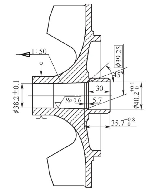
Step 4: Finish Boring of Tapered Bore
The central 1:50 tapered bore is finish-bored to achieve the required precision. Dimension chain analysis yields theoretical dimensions of 35.7 mm (+0.8, 0 mm) and 5.7 mm between the taper’s theoretical circle and the small end face. A taper plug gauge (φ39.25 mm × 1:50) is designed for inspection, using a coloring method to verify a contact fit of at least 60%. This ensures the tapered bore meets the stringent dimensional and geometric tolerances.
Step 5: Blade Machining and Inspection
A specialized lathe faceplate is designed to facilitate blade machining. The faceplate, mounted on the lathe spindle, supports auxiliary pads, positioning blocks, and the impeller. The end face and blade conical surfaces are machined, with the dimension L (53.5 mm, 0, -0.1 mm) measured using a depth micrometer from the positioning block’s large end face. This dimension serves as an indirect control for the closed-loop spatial dimension chain.
The blade’s spatial dimensions (53.5 mm (0, -0.1 mm), 5 mm (+0.2, +0.1 mm), φ225 mm, and 10°) are verified using a depth micrometer and a dedicated inspection template. The template’s structure includes pass and stop ends with dimensions and tolerances listed in Table 1. The inspection process employs a light-gap method, where the impeller is deemed acceptable if it satisfies the conditions simultaneously.
| Merkmal | Pass End (H) | Stop End (H) | Toleranz |
|---|---|---|---|
| Blade Spatial Dimension | 53.5 | 53.4 | 0, -0.1 |
| Blade Thickness | 5.2 | 5.0 | +0.2, +0.1 |
Inspection Template Design and Functionality
The inspection template is a critical tool for verifying the impeller’s spatial dimensions. Its structure is designed to measure the theoretical height of the non-continuous conical surface. The template includes pass and stop ends, with H values specified in Table 1. The light-gap inspection method ensures that the impeller’s blade dimensions fall within the acceptable tolerance range.
During inspection, the template is positioned against the impeller’s blade surfaces, and light is used to check for gaps. The minimum template condition, where the pass end must fit without obstruction. The maximum template condition, where the stop end must not pass, ensuring the impeller’s dimensions are within the specified tolerances. This method provides a reliable and efficient means of verifying complex spatial dimensions on the shop floor.
Validation and Performance
The described machining and inspection process has been validated through practical application. The use of dimension chain analysis, taper plug gauges, auxiliary gauges, and inspection templates ensures that the impeller’s complex spatial dimensions are consistently achieved. Online inspection is efficient, allowing for real-time verification during impeller machining. Assembly testing confirms that the impellers meet dimensional accuracy requirements, resulting in reliable performance and minimal interference in the pump assembly.
The process’s systematic approach, combining precise machining techniques with specialized inspection tools, guarantees high reliability and repeatability. The impeller’s dimensional accuracy directly contributes to the pump’s hydraulic efficiency and balance performance, ensuring long-term operational stability.
Schlussfolgerung
The machining and inspection process for marine pump impellers addresses the challenges of complex spatial dimension chains through a combination of dimension conversions, taper gauge design, and inspection templates. By implementing a multi-step machining process and specialized inspection tools, the process ensures high precision, reliability, and efficiency. The validated approach has proven effective in achieving the required dimensional accuracy, facilitating seamless assembly, and maintaining the performance of marine pump assemblies.