
Roots vacuum pump impellers are critical components in positive displacement vacuum pumps, known for their ability to handle high-volume gas transfer in various industrial applications. The precision machining of these impellers, typically featuring two or three lobed rotors, presents significant technical challenges due to their complex geometry, tight tolerances, and stringent performance requirements. This article provides a comprehensive, technical overview of the machining techniques used for Roots vacuum pump impellers, focusing on the processes, tools, and parameters involved, with an emphasis on achieving high precision, reliability, and performance.
Understanding the Roots Vacuum Pump Impeller
The impeller in a Roots vacuum pump, also referred to as a rotor, consists of two or three lobed components that rotate in opposite directions within a sealed chamber. These impellers feature an involute or epicycloid profile, which ensures minimal gas leakage while maintaining a vacuum state. The primary function of the impeller is to compress and transfer gas by creating a vacuum at the inlet, drawing gas into the pump chamber, and expelling it at the outlet. The precision of the impeller’s geometry directly impacts the pump’s efficiency, sealing performance, and durability.
The impellers are typically made from materials such as cast iron, stainless steel, or aluminum alloys, selected based on the application’s requirements, such as corrosion resistance or mechanical strength. The machining process must achieve dimensional accuracy within microns, maintain surface quality to minimize wear, and ensure precise alignment to prevent contact between rotating impellers or between impellers and the pump housing.
Key Machining Processes for Roots Vacuum Pump Impellers
The machining of Roots vacuum pump impellers involves multiple stages, each requiring specialized techniques and equipment. The primary processes include CNC machining, grinding, and finishing, with five-axis CNC machining being the most common due to the complex geometry of the impeller lobes. Below is a detailed breakdown of these processes.
CNC-Bearbeitung
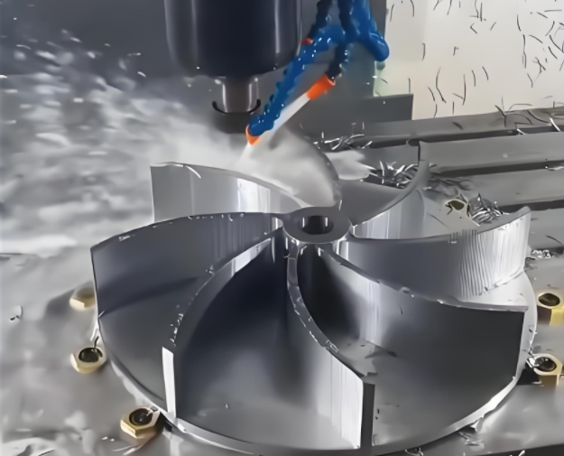
Computer Numerical Control (CNC) machining, particularly five-axis machining, is the cornerstone of impeller production due to its ability to handle complex, three-dimensional geometries. The process begins with the creation of a detailed CAD model, which defines the impeller’s involute or epicycloid profile, lobe curvature, and hub dimensions. The CAD model is then converted into a CNC program using CAM software, such as Siemens NX or Mastercam, to generate toolpaths.
Five-axis CNC machines are used to machine the impeller from a solid billet or a pre-cast blank. The machine’s ability to move the cutting tool along five axes allows for precise machining of the curved lobe surfaces and narrow channels between lobes. Typical machining parameters include:
| Parameter | Value |
|---|---|
| Spindeldrehzahl | 2,000–5,000 RPM |
| Vorschubgeschwindigkeit | 200–500 mm/min |
| Schnitttiefe | 0.5–2 mm (roughing), 0.1–0.3 mm (finishing) |
| Werkzeug-Typ | Ball-end mill, tapered ball-end mill |
The machining process is divided into three phases: roughing, semi-finishing, and finishing. Roughing removes excess material using a large-diameter tool, such as a bull-nose cutter, leaving a 0.5–1 mm allowance for subsequent stages. Semi-finishing refines the lobe surfaces, while finishing achieves the final dimensions and surface quality, often using smaller-diameter tools for intricate areas like the lobe roots.
Schleifen
After CNC machining, grinding is employed to achieve the required surface finish and dimensional accuracy. The involute or epicycloid profile of the impeller lobes requires high-precision grinding to ensure smooth surfaces and tight tolerances, typically within ±0.01 mm. Grinding is performed using CNC-controlled grinding machines equipped with diamond or cubic boron nitride (CBN) wheels, which are suitable for hard materials like stainless steel or cast iron.
Key grinding parameters include:
| Parameter | Value |
|---|---|
| Wheel Speed | 1,500–2,500 m/min |
| Vorschubgeschwindigkeit | 50–150 mm/min |
| Schnitttiefe | 0.005–0.02 mm |
| Oberfläche | Ra 0.2–0.4 µm |
Grinding ensures that the impeller surfaces are free of machining marks and have a low roughness value, which is critical for minimizing friction and wear during operation. The process also corrects minor dimensional deviations introduced during CNC machining.
Finishing and Polishing
Finishing and polishing are the final steps to achieve the desired surface quality and dimensional precision. Polishing is typically performed using abrasive compounds or polishing wheels to achieve a mirror-like finish, with surface roughness values as low as Ra 0.1 µm. This step is crucial for reducing gas leakage and improving the pump’s vacuum efficiency. In some cases, chemical polishing or electropolishing is used for stainless steel impellers to enhance corrosion resistance.
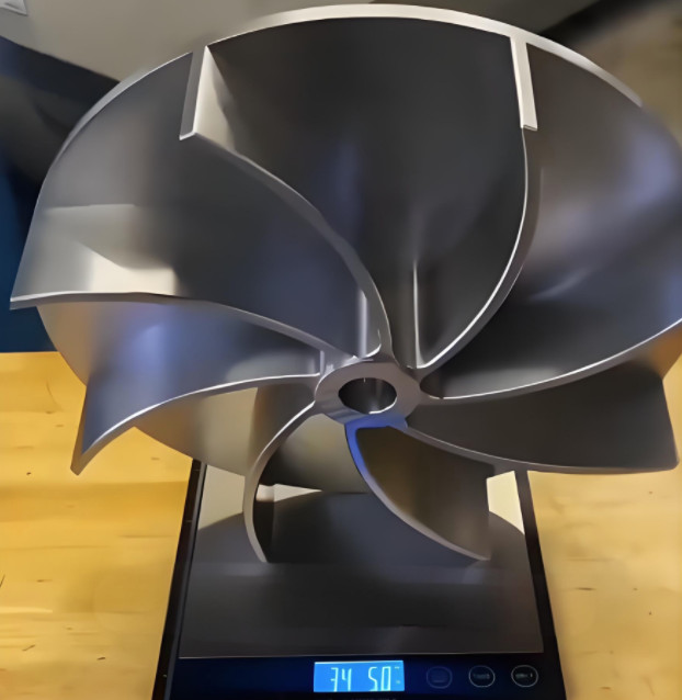
The finishing process also includes balancing the impeller to ensure even weight distribution and minimize vibration during high-speed rotation. Dynamic balancing is performed using specialized equipment, such as a balancing machine, to achieve a balance quality grade of G2.5 or better, as per ISO 1940-1 standards.
Technical Requirements for Precision Machining
The precision machining of Roots vacuum pump impellers must meet several technical requirements to ensure optimal performance. These include dimensional accuracy, surface quality, and geometric tolerances.
Dimensional Accuracy: The impeller’s dimensions, including lobe profile, hub diameter, and clearance between impellers, must be maintained within ±0.01 mm to ensure proper sealing and minimal gas leakage. The clearance between impellers and the pump housing is typically 0.05–0.1 mm, requiring precise machining to avoid contact during operation.
Oberflächenqualität: A smooth surface finish (Ra 0.2–0.4 µm) is essential to reduce friction, wear, and gas leakage. Surface imperfections, such as scratches or machining marks, can lead to turbulence in the gas flow, reducing pump efficiency.
Geometric Tolerances: The impeller’s lobe profile must adhere to strict geometric tolerances, such as parallelism and concentricity, to ensure smooth rotation and alignment. For example, the concentricity of the impeller hub to the lobe profile should be within 0.02 mm to prevent imbalance.
Tooling and Fixturing Considerations
The complex geometry of Roots vacuum pump impellers requires specialized tooling and fixturing to ensure stability and accuracy during machining. Ball-end mills and tapered ball-end mills are commonly used for machining the curved lobe surfaces, with tool diameters ranging from 3 mm to 10 mm depending on the impeller size. The choice of tool material, such as carbide or coated carbide, is critical for maintaining tool life and achieving the required surface finish.
Fixturing is equally important to prevent deformation or displacement during machining. A common approach is to use a shaft fixture that secures the impeller through its center hole, ensuring proper alignment and minimizing vibration. The fixture must be rigid enough to withstand cutting forces, particularly during roughing, where forces can exceed 500 N.
Quality Control and Inspection
Quality control is a critical aspect of impeller machining to ensure compliance with design specifications. Coordinate Measuring Machines (CMMs) are used to verify dimensional accuracy and geometric tolerances, with measurements taken at multiple points along the lobe profile and hub. Surface quality is assessed using profilometers to measure roughness, while ultrasonic or magnetic particle inspection is employed to detect subsurface defects, such as cracks or inclusions.
Dynamic balancing is performed to ensure the impeller meets the required balance quality grade. Any deviations detected during inspection are corrected through additional machining or grinding, ensuring the impeller meets all performance criteria before assembly into the pump.
Material Selection and Its Impact on Machining
The choice of material significantly influences the machining process. Common materials for Roots vacuum pump impellers include:
- Gusseisen: Offers good machinability and wear resistance but requires careful control of cutting parameters to avoid cracking.
- Rostfreier Stahl: Provides corrosion resistance but is harder to machine, requiring high-performance tools and lower cutting speeds.
- Aluminium-Legierungen: Lightweight and easy to machine but prone to deformation, necessitating precise fixturing.
The material’s hardness, toughness, and thermal conductivity dictate the selection of cutting tools, machining parameters, and coolant usage. For example, stainless steel impellers may require the use of high-pressure coolant to manage heat generation during machining.
Schlussfolgerung
The precision machining of Roots vacuum pump impellers is a complex process that demands advanced techniques, specialized equipment, and meticulous attention to detail. Five-axis CNC machining, grinding, and finishing are the primary processes used to achieve the required dimensional accuracy, surface quality, and geometric tolerances. By carefully selecting tools, fixtures, and machining parameters, manufacturers can produce impellers that meet the stringent requirements of vacuum pump applications. Quality control measures, including CMM inspection and dynamic balancing, ensure that the final product performs reliably in demanding industrial environments. This systematic approach to machining ensures the production of high-quality impellers that enhance the efficiency and durability of Roots vacuum pumps.