Rapid prototyping technologies have transformed the manufacturing of propeller blades, enabling faster design validation, precise fabrication, and cost-effective production. These technologies are critical in industries such as aerospace and marine engineering, where propeller blades require complex geometries, high precision, and robust material properties. This article provides a detailed examination of rapid prototyping methods suitable for propeller blade machining, focusing on their technical specifications, processes, and applications. The primary methods discussed include Computer Numerical Control (CNC) machining, additive manufacturing (3D printing), and hybrid approaches, with an emphasis on their practical implementation and parameters.
CNC Machining for Propeller Blade Fabrication
CNC machining is a subtractive manufacturing process widely used for propeller blade prototyping due to its ability to produce high-precision, fully dense metal components. It involves removing material from a solid workpiece using computer-controlled tools, such as mills or lathes, to achieve the desired geometry. For propeller blades, which often feature complex curves and thin sections, CNC machining offers exceptional accuracy and material versatility.
The process begins with a 3D CAD model of the propeller blade, typically created using software like CATIA V5 or SolidWorks. The CAD model is converted into CNC code using CAM software, such as MASTERCAM MILL X6, which generates tool paths for the machine. The code is then uploaded to a CNC machine via a post-processor. Common materials for propeller blades include Aluminiumlegierungen (e.g., Aluminium-24345, AlSi10Mg), stainless steel (e.g., 316L, 17-4 PH), and titanium alloys (e.g., Ti6Al4V), chosen for their corrosion resistance, lightweight properties, and strength.
CNC machining excels in producing propeller blades with tight tolerances, often achieving ±0.001 in. (0.025 mm) accuracy. For example, a 5-axis CNC turn-milling machine can handle the complex geometries of marine or aerospace propeller blades, allowing for simultaneous multi-axis cutting. Key parameters influencing the process include feed rate, step-over, and spindle speed. Studies have shown that higher feed rates (e.g., 400 mm/min) can increase dimensional deviations, while lower feed rates (e.g., 100 mm/min) improve accuracy but may extend production time.
| Parameter | Value Range | Impact |
|---|---|---|
| Vorschubgeschwindigkeit | 100–400 mm/min | Higher rates increase deviation; lower rates enhance accuracy |
| Step-Over | 0.1–0.5 mm | Smaller step-overs improve surface finish but increase machining time |
| Spindeldrehzahl | 10.000-20.000 U/MIN | Higher speeds suit softer materials like aluminum; lower speeds for harder alloys |
CNC machining is particularly effective for producing functional prototypes and small-batch production parts. It can fabricate internal features, such as cooling channels in turbine blades, which are challenging with other methods. However, setup complexity and material waste are considerations, as CNC machining removes excess material, unlike additive processes.

Additive Manufacturing (3D Printing) for Propeller Blades
Additive manufacturing, commonly known as 3D printing, builds propeller blades layer by layer from digital models, offering significant flexibility for complex geometries. Technologies like Fused Deposition Modeling (FDM), Stereolithography (SLA), Selective Laser Sintering (SLS), and Metal Additive Manufacturing (e.g., Direct Metal Laser Sintering, DMLS) are used for prototyping propeller blades. Each method suits different materials and applications, with specific advantages for rapid iteration and customization.
FDM is the most accessible 3D printing method, using thermoplastics like ABS, PLA, or nylon to create prototypes. It is cost-effective for initial design validation, with layer thicknesses typically ranging from 0.1 to 0.3 mm. However, FDM parts often have rough surface finishes (Ra 10–20 µm) and limited durability, making them less suitable for functional testing under high-stress conditions.
SLA uses a UV laser to cure liquid photopolymer resin, achieving high resolution (layer thickness 0.025–0.05 mm) and smooth surfaces (Ra 2–5 µm). It is ideal for creating detailed propeller blade models for aerodynamic testing or as master molds for casting. Materials like Tough Black (Loctite Henkel 3843) or Ceramic-Filled (BASF 3280) photopolymers enhance mechanical properties, though SLA parts are generally not suited for high-temperature or high-load applications.
SLS employs a CO2 laser to fuse powdered materials, such as nylon or metal powders, into solid parts. It produces robust prototypes with isotropic mechanical properties, suitable for functional testing. For example, SLS nylon parts can withstand mechanical stresses in UAV propeller testing, with layer thicknesses of 0.08–0.15 mm. Metal-based SLS (DMLS) is used for aluminum or titanium propeller blades, offering material properties comparable to wrought metals. Key parameters include laser power (200–400 W) and scan speed (500–1500 mm/s), which affect part density and strength.
| 3D Printing Method | Schichtdicke | Surface Roughness (Ra) | Typical Materials |
|---|---|---|---|
| FDM | 0,1-0,3 mm | 10–20 µm | ABS, PLA, Nylon |
| SLA | 0.025–0.05 mm | 2–5 µm | Photopolymer Resins |
| SLS/DMLS | 0.08–0.15 mm | 5–10 µm | Nylon, AlSi10Mg, Ti6Al4V |
Additive Fertigung enables rapid design iterations without tooling, reducing lead times to hours or days. For instance, a UAV propeller prototype can be 3D printed in 8–12 hours using FDM, compared to weeks for traditional machining. However, post-processing (e.g., bead blasting, dyeing) may be required to achieve desired surface quality, particularly for SLS parts.

Hybrid Rapid Prototyping Approaches
Hybrid rapid prototyping combines additive and subtractive methods to leverage the strengths of both. For propeller blade manufacturing, hybrid approaches integrate CNC machining with 3D printing to achieve high precision and complex geometries while minimizing material waste. A common hybrid method involves 3D printing a near-net-shape part, followed by CNC machining to refine critical surfaces and tolerances.
For example, a propeller blade can be 3D printed using DMLS to form a rough titanium or aluminum structure, then machined on a 5-axis CNC machine to achieve a surface finish of Ra 1.6 µm and tolerances of ±0.02 mm. This method reduces machining time by up to 50% compared to starting with a solid billet, as the 3D-printed part is already close to the final shape. The process is particularly useful for aerospace turbine blades, where internal cooling channels are printed, and external surfaces are machined for aerodynamic precision.
Another hybrid approach uses 3D-printed master models to create silicone molds for vacuum casting, which is then followed by CNC machining to enhance dimensional accuracy. Vacuum casting can replicate propeller blade prototypes in polyurethane or other resins, with mold tolerances of ±0.1 mm. CNC machining then refines the cast part to meet stricter requirements, such as ±0.05 mm for marine propeller blades.
Hybrid methods require careful integration of CAD/CAM workflows. The 3D-printed part’s geometry must be designed to accommodate machining allowances, typically 0.5–1 mm of excess material. Software like Siemens NX or Autodesk Fusion 360 can simulate the hybrid process, ensuring compatibility between additive and subtractive steps. This approach is highly effective for low-volume production and prototyping, offering a balance of speed, precision, and material efficiency.
Applications in Aerospace and Marine Industries
Rapid prototyping technologies are extensively applied in aerospace and marine industries for propeller blade development. In aerospace, CNC machining and DMLS are used to prototype turbine blades with internal cooling channels, achieving dimensional accuracies of ±0.02 mm and material properties suitable for high-temperature environments (up to 1000°C). These prototypes undergo rigorous testing for structural integrity and aerodynamic performance before full-scale production.
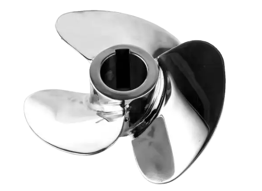
In marine engineering, rapid prototyping facilitates the fabrication of propeller blades for ships and unmanned aerial vehicles (UAVs). For instance, a 3-blade marine propeller made from Aluminium-24345 can be CNC machined with a feed rate of 200 mm/min and step-over of 0.2 mm to achieve a surface roughness of Ra 3.2 µm. Alternatively, FDM-printed PLA propellers are used for UAVs, with prototypes tested for thrust and torque using custom testing apparatus. These applications demonstrate the versatility of rapid prototyping in meeting industry-specific requirements.
The process typically involves several steps: conceptualization and CAD modeling, material and method selection, prototyping, testing, and iteration. For example, a marine propeller blade’s CAD model is scanned using 3D photo-scanning to verify geometric accuracy, with deviations as low as 0.05 mm achieved through optimized CNC parameters. These steps ensure that prototypes meet stringent operational demands before production scaling.

Material Selection and Considerations
Material choice is critical in rapid prototyping for propeller blades, as it affects performance, durability, and manufacturability. Aluminum alloys (e.g., AlSi10Mg, Aluminium-24345) are favored for their lightweight, corrosion-resistant properties, with tensile strengths of 300–400 MPa. Titanium alloys (e.g., Ti6Al4V) offer superior strength-to-weight ratios (yield strength 800–900 MPa) and are used in high-performance aerospace blades. Thermoplastics like nylon and PLA are suitable for FDM prototyping, while photopolymers and metal powders are used in SLA and DMLS, respectively.
Material properties must align with prototyping goals. For visual prototypes, PLA or ABS suffices, with tensile strengths of 50–70 MPa. For functional prototypes, metal alloys or high-performance resins (e.g., BASF 3280) are preferred, offering tensile strengths up to 200 MPa for resins and 1000 MPa for metals. Material selection also depends on the prototyping method, as CNC machining supports a broader range of metals and plastics compared to 3D printing.
Schlussfolgerung
Rapid prototyping technologies, including CNC machining, additive manufacturing, and hybrid approaches, provide robust solutions for propeller blade fabrication. CNC machining offers unparalleled precision for metal blades, achieving tolerances of ±0.001 in., while 3D printing enables rapid iteration and complex geometries with layer thicknesses as low as 0.025 mm. Hybrid methods combine the strengths of both, reducing production time and material waste. These technologies are integral to aerospace and marine industries, enabling efficient prototyping and testing of propeller blades with high accuracy and performance. By leveraging advanced CAD/CAM workflows and optimized parameters, manufacturers can produce reliable prototypes that meet stringent industry standards.
