CNC 5-axis machining is a critical technology for manufacturing complex components like impellers, widely used in aerospace, automotive, and energy industries. Impellers, with their intricate geometries such as twisted blades and deep flow channels, demand high precision and efficiency. This article provides a comprehensive, technical overview of the key points in CNC 5-axis machining of impellers, focusing on tool path planning, machine setup, material considerations, and deformation control. Detailed parameters and structured insights ensure a systematic understanding of the process.
Understanding CNC 5-Axis Machining
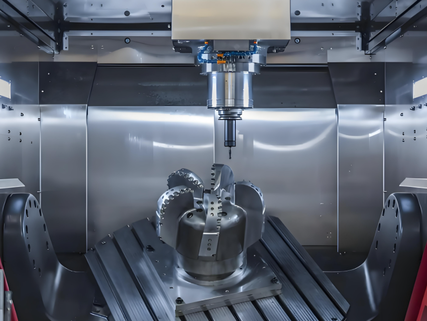
CNC 5-axis machining involves tools or workpieces moving along five axes: three linear (X, Y, Z) and two rotational (typically A and B or C). This capability allows machining complex geometries in a single setup, reducing errors and improving efficiency. For impellers, 5-Achsen-Bearbeitung is essential due to their free-form surfaces, thin blades, and tight tolerances. The process relies on advanced CAD/CAM software to generate G-code, which directs the machine’s movements.
The primary advantage of 5-axis machining over 3-axis is the ability to access five sides of a workpiece without repositioning. This is particularly beneficial for impellers, where blades require precise cuts at varying angles. The technology supports industries requiring high-performance components, such as turbine blades, compressors, and turbochargers.
Key Technical Points in Impeller Machining
Machining impellers using 5-axis CNC involves several critical technical aspects. These include tool path planning, machine configuration, material selection, cutting parameters, and deformation control. Each aspect is detailed below with a focus on precision and efficiency.
Tool Path Planning
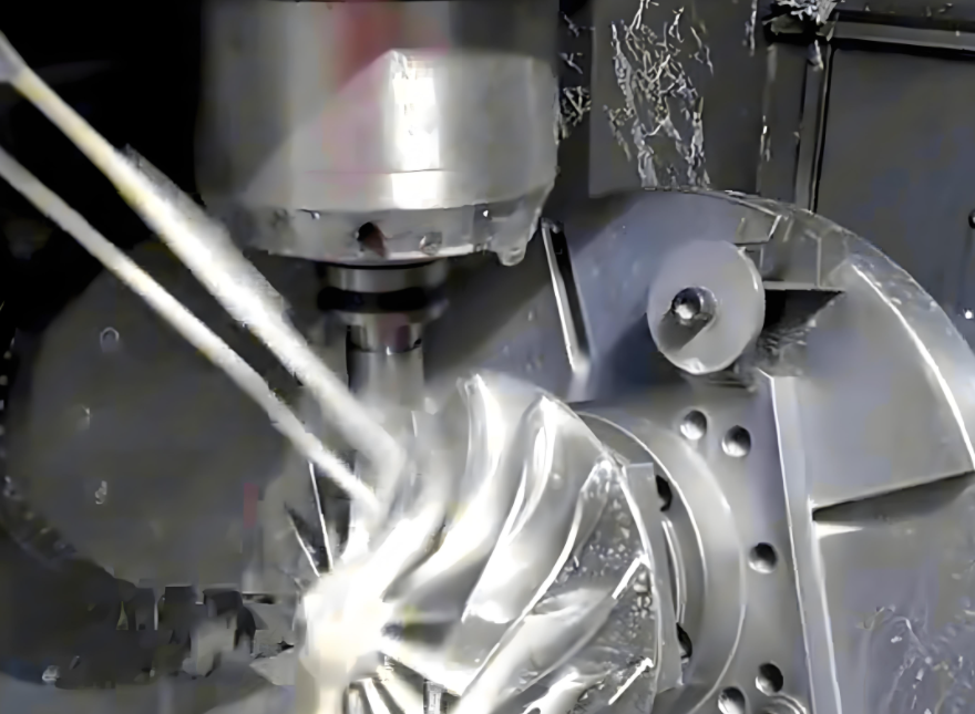
Tool path planning is the cornerstone of successful impeller machining. Impellers feature complex geometries, such as twisted blades and narrow flow channels, which challenge conventional machining. The tool path must avoid interference, ensure smooth surface finishes, and optimize machining time.
- Path Generation: CAD/CAM software, such as UG-NX or SolidWorks, converts 3D impeller models into tool paths. Non-Uniform Rational B-Spline (NURBS) curves are often used to define blade surfaces, enabling precise tool trajectories.
- Roughing Strategies: Plunge roughing removes excess material between blades efficiently. The step-over distance typically ranges from 0.5 to 1.5 mm, depending on material hardness and tool diameter (e.g., 10–20 mm for steel impellers).
- Finishing Strategies: Swarf cutting ensures smooth blade surfaces by aligning the tool axis with the blade’s curvature. A step-over distance of 0.1–0.3 mm is common for finishing to achieve surface roughness (Ra) of 0.8–1.6 µm.
- Interference Avoidance: The tool must avoid collisions with adjacent blades or the hub. Advanced CAM systems simulate tool paths to detect potential interferences, adjusting the tool axis dynamically.
Recent advancements, such as the SA-PSO (Simulated Annealing-Particle Swarm Optimization) algorithm, optimize tool paths by minimizing over-cutting or under-cutting, achieving machining accuracy errors as low as 0.007–0.012 mm.
Machine Configuration
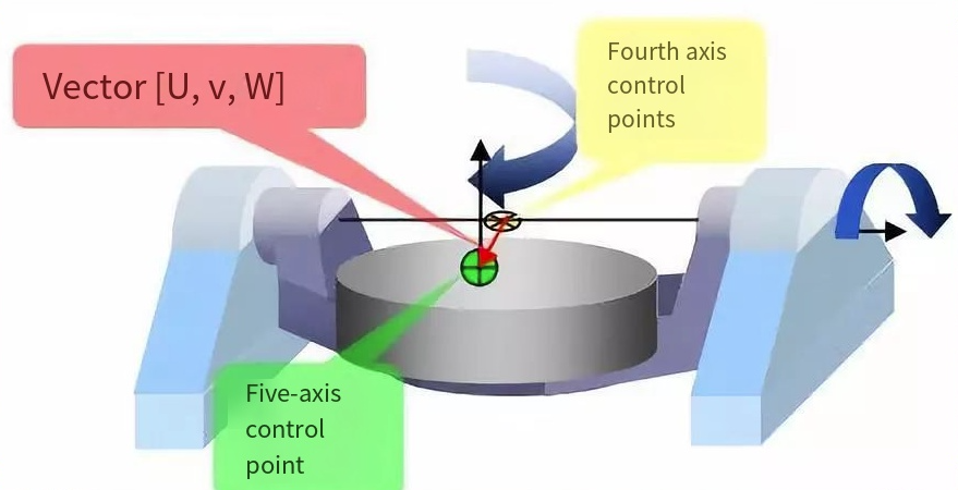
The choice of machine configuration impacts impeller machining quality. Two primary 5-axis configurations are used: trunnion-style and swivel-rotate-style.
| Configuration | Beschreibung | Vorteile | Anwendungen |
|---|---|---|---|
| Trunnion-Style | A-axis rotates around X-axis, C-axis around Z-axis; table movement expresses rotation. | Suitable for larger workpieces; no compensation needed for spindle swivel space. | Heavy impellers for turbines, compressors. |
| Swivel-Rotate-Style | B-axis rotates around Y-axis, C-axis around Z-axis; spindle swivels for rotation. | Supports heavier parts; maintains horizontal table during cutting. | Turbocharger impellers, aerospace components. |
Key machine parameters include spindle speed (10,000–20,000 RPM for high-speed machining), torque (50–150 Nm for tough materials like titanium), and axis synchronization accuracy (±0.005° for rotational axes). Closed-loop feedback systems with encoders ensure precise positioning.
Material Selection and Challenges
Impellers are often made from high-strength, heat-resistant alloys like titanium, Inconel, or stainless steel, which pose machining challenges due to their hardness and low thermal conductivity.
- Titan-Legierungen: Used in aerospace impellers, titanium requires low cutting speeds (50–80 m/min) and high feed rates (0.05–0.1 mm/tooth) to minimize heat buildup.
- Inconel: Common in turbochargers, Inconel demands coated carbide tools with a rake angle of 10–15° and coolant pressure of 50–70 bar to reduce tool wear.
- Rostfreier Stahl: Easier to machine but requires careful control of cutting forces to avoid work hardening. Cutting speeds of 100–150 m/min are typical.
Material properties dictate tool selection, with shorter tools (length-to-diameter ratio < 4:1) preferred to reduce vibration and ensure rigidity.
Schnittparameter
Optimal cutting parameters balance machining efficiency and part quality. The following table outlines typical parameters for impeller machining:
| Parameter | Aufrauen | Fertigstellung |
|---|---|---|
| Spindle Speed (RPM) | 8,000–15,000 | 15,000–20,000 |
| Feed Rate (mm/min) | 1,000–2,000 | 500–1,000 |
| Cutting Depth (mm) | 1.0–3.0 | 0.1–0.5 |
| Step-Over Distance (mm) | 0.5–1.5 | 0.1–0.3 |
These parameters vary based on material and tool type. For example, titanium requires lower speeds and feeds to prevent tool overheating, while stainless steel allows higher speeds for efficiency.
Deformation Control
Impeller blades, being thin and twisted, are prone to deformation due to cutting forces and thermal effects. Effective deformation control strategies include:
- Optimierung der Werkzeugwege: Use of adaptive tool paths that adjust feed rates based on blade thickness, reducing forces on thin sections.
- Fixture Design: Custom fixtures with distributed clamping points minimize vibration. Vacuum fixtures or soft jaws are common for delicate impellers.
- Error Compensation: CAM software compensates for tool wear and machine dynamics, maintaining tolerances within ±0.005 mm.
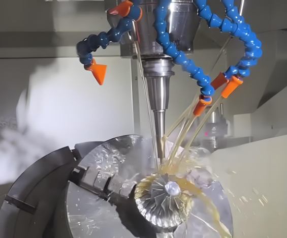
- Coolant Application: High-pressure coolant (50–100 bar) reduces thermal deformation, especially for heat-sensitive materials like titanium.
Simulation software, such as Vericut, models the entire machining envelope to predict and mitigate deformation risks.
Applications of 5-Axis Machining for Impellers
5-axis machining is indispensable for impeller production across multiple industries:
- Luft- und Raumfahrt: Manufacturing turbine blades and compressor impellers with tolerances of ±0.01 mm for aerodynamic performance.
- Automobilindustrie: Producing turbocharger impellers with complex blade geometries for high efficiency.
- Energy: Crafting impellers for power generators and pumps, requiring durability under high-pressure conditions.
The ability to machine intricate designs in a single setup makes 5-axis CNC ideal for rapid prototyping and high-volume production.
Herausforderungen und Lösungen
Despite its advantages, 5-axis machining of impellers faces challenges:
- Complex Tool Path Calculation: Addressed by advanced CAM systems with real-time simulation and interference checking.
- High Computational Load: Optimized algorithms like SA-PSO reduce processing time for tool path generation.
- Werkzeugverschleiß: Coated tools and optimized cutting parameters extend tool life, with tool wear monitoring systems providing real-time feedback.
These solutions enhance machining reliability and part quality.
Future Trends in 5-Axis Impeller Machining
Advancements in 5-axis machining are shaping the future of impeller production:
- STEP-NC Integration: Enables machine-independent tool paths, improving flexibility and reducing setup time.
- AI-Driven Optimization: Machine learning algorithms optimize tool paths and predict deformation, enhancing precision.
- Hybrid Manufacturing: Combining 5-axis machining with additive manufacturing for complex impellers with internal features.
These trends promise greater efficiency and adaptability in impeller manufacturing.
Schlussfolgerung
CNC 5-axis machining is the preferred method for impeller production due to its ability to handle complex geometries with high precision. Key technical points include tool path planning, machine configuration, material selection, cutting parameters, and deformation control. By leveraging advanced CAD/CAM systems, optimized parameters, and innovative algorithms, manufacturers can achieve superior surface finishes, tight tolerances, and efficient production. As technology evolves, 5-axis machining will continue to drive advancements in impeller manufacturing across critical industries.