Designing machining fixtures for drum fan blades requires precision, stability, and adaptability to ensure high-quality production. Drum fan blades, integral to industrial and HVAC systems, demand fixtures that can accommodate complex geometries, withstand cutting forces, and maintain dimensional accuracy. This article provides a comprehensive guide to fixture design techniques, emphasizing practical, experience-based methods to achieve reliable and efficient machining processes.
Understanding Drum Fan Blade Geometry and Machining Requirements
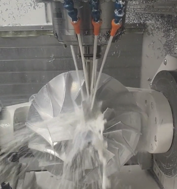
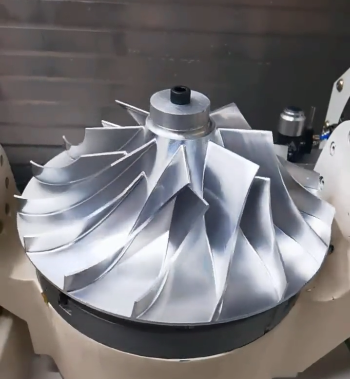
Drum fan blades typically feature complex, curved profiles with varying thicknesses and aerodynamic shapes. These blades are often made from materials like aluminum, stainless steel, or composites, each presenting unique machining challenges. The fixture must securely hold the blade, minimize deformation, and allow precise tool access.
Key considerations include:
- Geometrie der Klinge: Blades may have airfoil-like profiles with twist angles ranging from 10° to 30° and chord lengths between 50 mm and 200 mm, depending on the fan size.
- Materialeigenschaften: Aluminum blades (e.g., 6061-T6) require fixtures that prevent scratching, while stainless steel (e.g., 304) demands higher clamping forces due to its hardness (up to 200 HB).
- Machining Operations: Common operations include milling, drilling, and finishing, with tolerances as tight as ±0.05 mm for critical surfaces.
Fixtures must align the blade’s datum points, typically the root or hub interface, to ensure repeatability. For example, a blade with a 100 mm chord length may require locating points at the root with a positional tolerance of ±0.02 mm to maintain aerodynamic performance.
Principles of Fixture Design for Drum Fan Blades
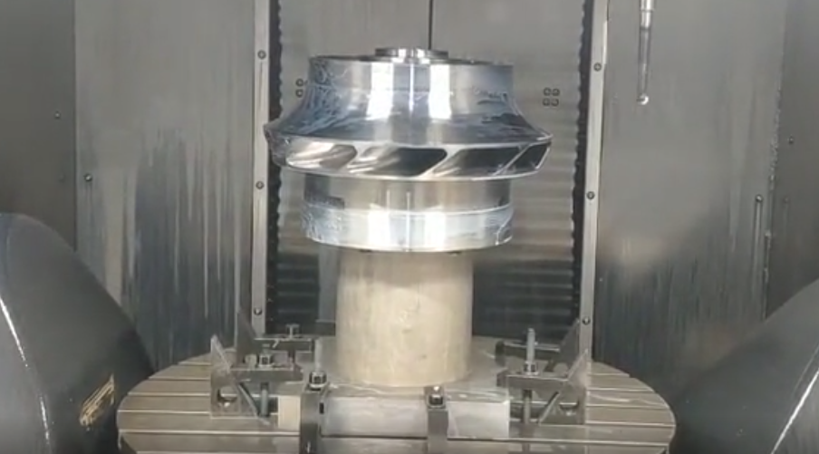
Effective fixture design follows the 3-2-1 locating principle to constrain the workpiece’s six degrees of freedom. For drum fan blades, this principle is adapted to accommodate curved surfaces and thin-walled structures.
Locating: Three primary locators are placed on the blade’s root or base to restrict translation in the Z-axis and rotation about the X and Y axes. Two locators on a secondary plane, often the blade’s edge, restrict translation in the Y-axis and rotation about the Z-axis. A single locator on the tertiary plane restricts translation in the X-axis.
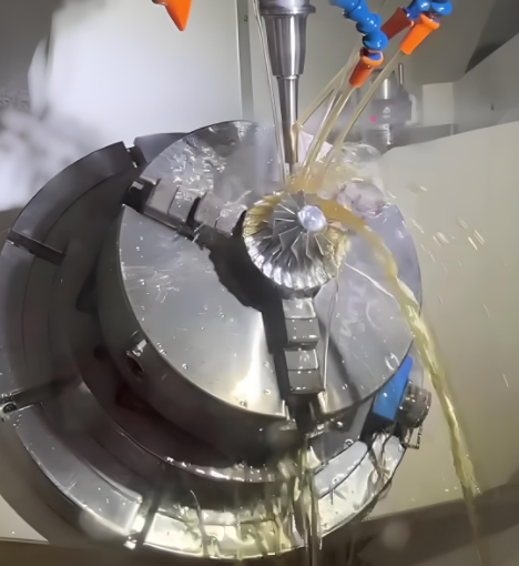
Clamping: Clamps must apply sufficient force to resist cutting forces, typically ranging from 500 N to 2000 N for milling operations, without deforming the blade. Hydraulic or pneumatic clamps are preferred for their uniform force distribution, achieving pressures up to 10 MPa.
Support: Thin blades (e.g., 2-5 mm thick) require additional supports to prevent vibration. Compliant supports, such as adjustable pads, can reduce deflection by up to 80% compared to rigid supports.
Fixtures should also allow for tool clearance, typically requiring a minimum of 10 mm around the blade’s periphery for a 5-axis CNC machine.
Material Selection for Fixtures
Fixture materials must balance strength, durability, and cost. Common choices include:
| Material | Eigenschaften | Application |
|---|---|---|
| Tool Steel (AISI D2) | Hardness: 58-62 HRC, High wear resistance | Locators and clamps for high-precision machining |
| Aluminum (6061-T6) | Lightweight, Yield strength: 276 MPa | Base plates for reduced fixture weight |
| Polyurethane | Shore hardness: 60-90A, Vibration damping | Compliant supports for thin blades |
Tool steel is ideal for high-wear components, while aluminum reduces fixture weight, improving setup efficiency. Polyurethane supports absorb vibrations, reducing chatter during machining.
Design Techniques for Precision and Stability
Modular Fixture Design: Modular fixtures, using standardized components like T-slot bases, allow quick reconfiguration for different blade sizes. For example, a modular fixture can accommodate blades with chord lengths from 80 mm to 150 mm by adjusting locator positions.
Hydraulic Clamping Systems: Hydraulic clamps provide consistent force, reducing setup time by 30-50% compared to manual clamps. A typical system operates at 5-7 MPa, ensuring secure holding without blade deformation.
Vacuum Fixtures: For thin composite blades, vacuum fixtures can apply uniform pressure (up to 0.1 MPa) across the blade surface, minimizing distortion. These are particularly effective for blades with thicknesses below 3 mm.
Finite Element Analysis (FEA): FEA is used to simulate clamping and cutting forces. For a blade under 1000 N cutting force, FEA can predict deflections within 0.01 mm, ensuring fixture designs meet tolerance requirements.
Anti-Vibration Features: Incorporating damping elements, such as rubber pads or viscoelastic layers, reduces vibration amplitude by up to 60%, improving surface finish quality to Ra 0.8 µm or better.
Manufacturing and Assembly of Fixtures
Fixtures are typically machined using CNC milling to achieve tolerances of ±0.01 mm for locator surfaces. Assembly involves aligning locators to datum points using coordinate measuring machines (CMM). For example, a CMM can verify locator positions with an accuracy of 0.005 mm.
Key steps include:
- Base Plate Machining: Mill the base plate to a flatness of 0.02 mm to ensure stability.
- Locator Installation: Secure locators with bolts torqued to 50-70 Nm to prevent movement.
- Clamp Integration: Install hydraulic or pneumatic clamps with a repeatability of ±0.01 mm.
- Support Placement: Position adjustable supports to contact the blade at points of maximum deflection, identified via FEA.
Post-assembly, fixtures are tested for repeatability by loading and unloading a sample blade 10-20 times, ensuring positional accuracy within 0.02 mm.
Fixture Maintenance and Quality Control
Regular maintenance ensures fixture reliability. Key practices include:
- Inspektion: Check locator wear every 1000 cycles using a CMM to detect deviations beyond 0.01 mm.
- Cleaning: Remove chips and coolant residue to prevent surface damage to blades.
- Schmierung: Apply lubricant to moving parts, such as hydraulic pistons, to maintain smooth operation.
Quality control involves verifying machined blades against tolerances using a three-coordinate measuring machine. For example, a blade’s profile tolerance of ±0.1 mm is checked at cross-sections 30 mm and 60 mm from the root.
Case Study: Fixture Design for a 120 mm Chord Blade
For a stainless steel blade with a 120 mm chord length and 3 distinctive feature of fixture design is the use of multiple locators and clamps to ensure stability and precision during machining. For a 120 mm chord blade, a fixture might include:
| Component | Specifications |
|---|---|
| Base Plate | 6061-T6 Aluminum, 300 x 200 x 20 mm, Flatness: 0.02 mm |
| Locators | AISI D2 Steel, 3 primary, 2 secondary, 1 tertiary, Tolerance: ±0.01 mm |
| Clamps | Hydraulic, 6 MPa, Repeatability: ±0.01 mm |
| Supports | Polyurethane, Shore 80A, 4 adjustable pads |
The fixture was designed using FEA to minimize deflection under a 1500 N milling force, achieving a maximum deflection of 0.015 mm. The blade was machined to a surface finish of Ra 0.6 µm and a profile tolerance of ±0.08 mm, meeting aerospace standards.
Schlussfolgerung
Designing machining fixtures for drum fan blades requires a systematic approach, balancing precision, stability, and efficiency. By understanding blade geometry, selecting appropriate materials, and employing advanced techniques like hydraulic clamping and FEA, manufacturers can achieve high-quality results. Regular maintenance and quality control ensure consistent performance, making these techniques essential for reliable production.