Comprehensive study on optimizing tool paths for turbine impeller machining with Swiss Mikron five-axis CNC machines, emphasizing technical parameters and systematic methodologies.
Overview of Five-Axis Machining for Turbine Impellers
Five-axis machining is essential for manufacturing complex components like turbine impellers, which feature twisted blades and free-form surfaces. Swiss Mikron machines, such as the UCP710 model, are widely used due to their precision and flexibility in handling intricate geometries. The primary goal of tool path optimization is to enhance machining efficiency, improve surface quality, and minimize tool wear while ensuring geometric accuracy.
Turbine impellers, critical in aerospace and energy industries, require high precision due to their aerodynamic performance demands. The five-axis configuration allows simultaneous movement along three translational axes (X, Y, Z) and two rotational axes (A, C), enabling the tool to approach the workpiece from various angles. This capability is vital for machining the complex, thin-walled, and twisted surfaces of impellers.
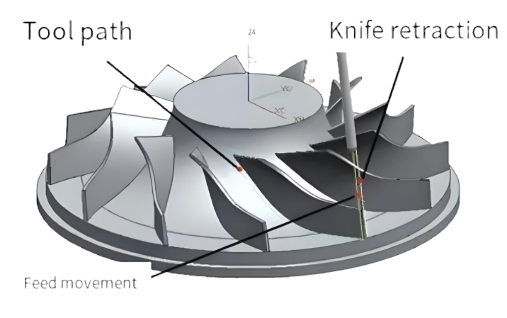
Tool path optimization involves generating cutter location (CL) data that minimizes machining time, avoids collisions, and ensures smooth tool movements. The process includes roughing, semi-finishing, and finishing stages, each requiring specific strategies to achieve the desired outcome.

Key Parameters in Tool Path Optimization
Effective tool path optimization for turbine impellers on Swiss Mikron five-axis machines relies on precise control of several machining parameters. These parameters are tailored to the impeller’s geometry, material, and the machine’s kinematic capabilities.
Schnittparameter
Cutting parameters directly influence machining efficiency and surface quality. The following table outlines typical parameters used for machining turbine impellers made of alloy steel (e.g., EN 34CrNiMo6) on a Mikron UCP710:
| Parameter | Value | Beschreibung |
|---|---|---|
| Spindeldrehzahl | 12,000–15,000 RPM | High-speed milling to reduce cutting forces and improve surface finish. |
| Vorschubgeschwindigkeit | 1,500–2,500 mm/min | Balanced to minimize tool wear while maintaining efficiency. |
| Schnitttiefe | 0,5-1,5 mm | Shallow cuts for finishing to ensure precision. |
| Step-Over | 0.2–0.4 mm | Small step-over for smooth surface and reduced scallop height. |
These parameters are adjusted based on the tool type (e.g., flat-end or ball-end cutters) and the machining stage. For instance, roughing may use higher depth of cut (2–3 mm) and larger step-over (0.8–1.2 mm) to remove material quickly.
Tool Orientation and Kinematics
Tool orientation optimization is critical to avoid collisions and minimize rotary axis movements, which can cause vibrations and affect surface quality. The Mikron UCP710, a tilting-rotary-table type machine, allows precise control of tool tilt and yaw angles. Optimal tool orientation is achieved by maintaining a lead/tilt angle of approximately 15° during finishing, as this reduces cutting forces and improves surface integrity.
Inverse kinematics models are used to map tool paths to machine coordinates, ensuring smooth transitions between cutter contact (CC) points. The angular acceleration of rotary axes is limited to 100 rad/s² to prevent dynamic instability. Algorithms, such as those based on NURBS (Non-Uniform Rational B-Splines), are employed to smooth tool paths and reduce reverse movements that cause tool marks.
Cutter Runout Consideration
Cutter runout, a common issue in five-axis machining, affects geometric accuracy by causing deviations in the tool’s cutting edge position. To mitigate this, tool path optimization incorporates runout models with parameters such as cutter axis tilt (0.01–0.05 mm) and offset (0.02–0.08 mm). Analytical envelope surface models are used to redesign tool paths, reducing geometry errors by up to 70% compared to unoptimized paths.
Tool Path Generation Strategies
Tool path generation for turbine impellers involves multiple strategies tailored to roughing, semi-finishing, and finishing. Each stage addresses specific requirements, such as material removal rate, surface quality, and tool life.
Roughing Strategies
Roughing aims to remove excess material efficiently while leaving uniform stock for subsequent stages. The Mikron UCP710 employs 3+2 machining techniques for roughing, where the tool is fixed at specific angles to simplify kinematics. A common approach is cavity milling with multi-blade roughing, using tapered ballnose cutters (diameter: 10–16 mm, taper angle: 3°–5°).
The machining area is divided into sub-regions based on hub and shroud curves, allowing larger tool diameters (up to 20 mm) in open areas to increase material removal rates. Tool paths follow a zigzag pattern with a step-over of 1.0–1.5 mm and a depth of cut of 2.5–3.5 mm. This strategy reduces machining time by 20% compared to simultaneous five-axis roughing.
Semi-Finishing Strategies
Semi-finishing prepares the surface for final machining by reducing stock to 0.3–0.5 mm. Contour-parallel tool paths are preferred, as they maintain consistent scallop heights (0.01–0.02 mm). Flat-end cutters (diameter: 8–12 mm) are used with a step-over of 0.4–0.6 mm and a feed rate of 2,000 mm/min. The tool axis is dynamically adjusted to avoid collisions, using a lead angle of 10°–15°.
Material removal simulation, integrated with machine kinematics, ensures accurate stock distribution. This approach minimizes overcuts and undercuts, improving surface quality for the finishing stage.
Finishing Strategies
Finishing focuses on achieving high surface quality (Ra: 0.4–0.8 μm) and geometric accuracy (±0.02 mm). Flank milling with tapered ballnose cutters (diameter: 6–10 mm, taper angle: 2°–4°) is commonly used for impeller blades. The tool path follows a spiral pattern, maintaining a constant step-over of 0.2–0.3 mm to minimize cusp heights.
Collision-free tool paths are generated using geometric algorithms that detect interference between the tool and workpiece. The CL data are smoothed to eliminate reverse movements, reducing tool marks. Finishing time is optimized by limiting rotary axis jerk to 500 rad/s³, ensuring smooth tool motion.
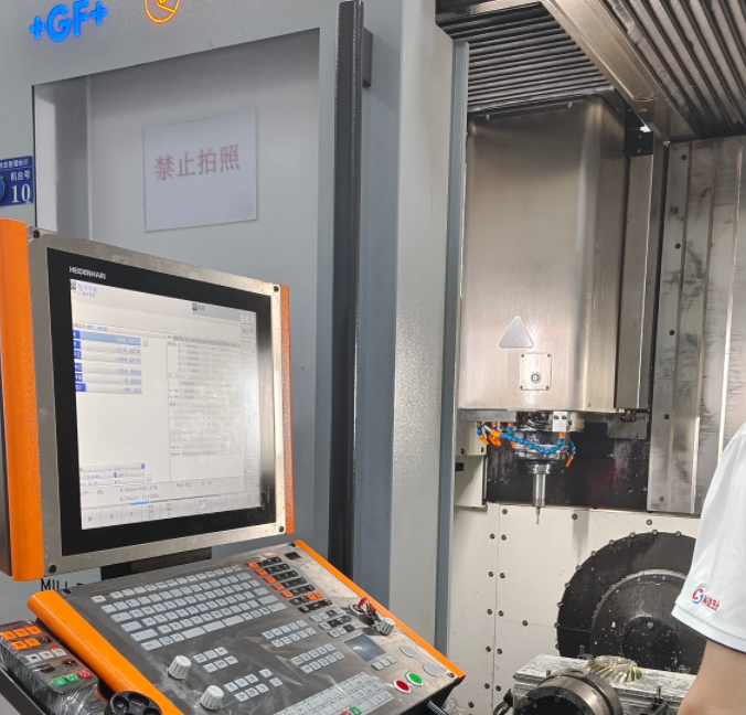
Practical Implementation on Swiss Mikron Machines
Implementing optimized tool paths on Swiss Mikron machines requires integration with CAD/CAM software, such as Unigraphics NX or MasterCAM. The process involves several steps:
- Geometry Modeling: The impeller’s 3D model is created, defining hub, shroud, and blade surfaces using NURBS or STL formats.
- Tool Path Generation: CAM software generates CL data based on optimized parameters, incorporating machine kinematics and runout models.
- Post-Processing: CL data are converted into NC code tailored to the Mikron UCP710’s controller, ensuring accurate axis movements.
- Simulation and Verification: Virtual machining simulations validate tool paths, detecting collisions and estimating machining time.
- Machining and Inspection: The impeller is machined, and surface quality is verified using a 3D coordinate measuring machine (CMM).
A case study involving a centrifugal impeller (diameter: 200 mm, blade height: 50 mm) machined on a Mikron UCP710 demonstrated a 23% reduction in finishing time (from 120 to 92 minutes) and improved surface roughness (Ra: 0.6 μm) compared to conventional tool paths.
Difficulties in Tool Path Optimization
While tool path optimization enhances machining performance, certain difficulties arise during implementation:
- Komplexe Geometrie: The twisted and thin-walled nature of impeller blades complicates tool path planning, increasing the risk of collisions and gouging.
- Cutter Runout: Uncompensated runout leads to geometric errors, requiring advanced modeling to mitigate its effects.
- Machine Dynamics: High-speed machining induces vibrations, necessitating precise control of rotary axis accelerations and jerks.
These issues are addressed through rigorous simulation, parameter tuning, and algorithm development, ensuring robust tool paths.
Schlussfolgerung
Tool path optimization for five-axis machining of turbine impellers on Swiss Mikron machines is a systematic process that enhances efficiency, precision, and surface quality. By carefully controlling cutting parameters, tool orientation, and machining strategies, manufacturers can achieve significant improvements in performance. Practical implementation involves integrating advanced CAD/CAM tools, rigorous simulation, and precise machine control. Despite challenges like complex geometries and cutter runout, optimized tool paths deliver reliable results, as demonstrated by real-world case studies.