Five-axis machining is essential for manufacturing gas turbine impellers, which require high precision due to their complex geometries and critical performance demands. This guide provides a detailed, technical overview of programming techniques, focusing on practical methods to achieve accuracy, efficiency, and quality. Drawing from industry practices, it emphasizes tool path optimization, cutter selection, and inspection processes, ensuring reliability and professionalism.
Understanding Five-Axis Machining for Gas Turbine Impellers
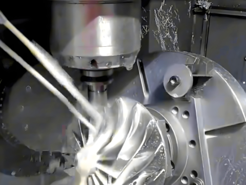
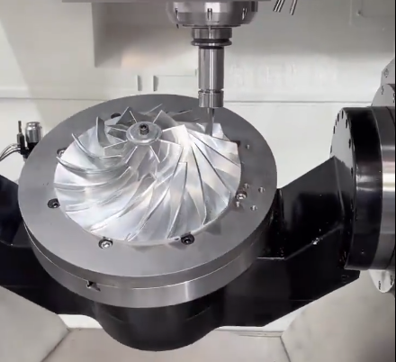
Five-axis machining involves simultaneous movement along three linear axes (X, Y, Z) and two rotational axes (A and B or C), allowing the cutting tool to approach the workpiece from multiple angles. Gas turbine impellers, typically made from titanium or nickel-based superalloys, feature intricate, curved blades with complex hub and shroud geometries. These components demand enge Toleranzen (e.g., ±0.015 mm) to ensure aerodynamic performance and structural integrity. Machines like the DMG MORI DMU 50 or Hermle C 42 provide the rigidity and control required for these tasks.
The impeller’s geometry, including twisted blades and variable curvature, necessitates five-axis machining to minimize setups and achieve smooth surface finishes. Programming must account for material properties, such as high hardness (e.g., 38-42 HRC for Inconel), and thermal stresses during machining.
Tool Path Generation and Optimization
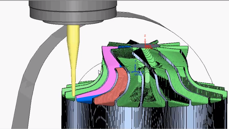
Tool path generation is critical for machining gas turbine impellers. CAD/CAM software like Siemens NX, PowerMill, or hyperMILL is used to create and optimize tool paths based on a 3D impeller model defining blade profiles, hub, and shroud surfaces.
Key techniques include:
- Blade-by-Blade Machining: Programs individual blades using segmented tool paths, ensuring precise control over each surface. For instance, Siemens NX’s Impeller Machining module supports blade-specific paths, reducing machining time by 10-15%.
- Swarf Cutting: Aligns the tool’s side with the blade’s ruled surface, minimizing scalloping and achieving surface roughness (Ra) below 0.6 µm.
- Trochoidal Milling: Uses circular tool paths for roughing, reducing tool load and heat generation. This method extends tool life by up to 25% when machining superalloys.
Optimization parameters include step-over distance (0.1-0.4 mm for finishing), feed rate (80-250 mm/min for titanium), and spindle speed (10,000-15,000 RPM). Post-processors convert CAM tool paths into G-code, ensuring compatibility with CNC controllers like Heidenhain or Fanuc.
Cutter Selection and Tooling Strategies
Selecting appropriate cutting tools is vital for impeller machining. Tool geometry, material, and coating directly affect performance. Common tools include:
| Werkzeug-Typ | Application | Parameter |
|---|---|---|
| Ball End Mill | Finishing blade surfaces | Diameter: 4-8 mm, Corner Radius: 0.3 mm, Flutes: 4 |
| Conical Barrel Cutter | Roughing and finishing curved surfaces | Radius: 40-80 mm, Taper Angle: 3-8°, Flutes: 3-4 |
| Lollipop Cutter | Machining hub undercuts | Diameter: 6-10 mm, Neck Length: 30-50 mm |
Conical barrel cutters, supported by PowerMill’s impeller machining strategies, reduce finishing time by 20% due to larger contact areas. Lollipop cutters access tight hub regions, maintaining tolerances within ±0.01 mm. Tool orientation uses lead angles (8-12°) and tilt angles (3-7°) to minimize vibration. Tool wear monitoring, integrated into CAM systems, adjusts feed rates to maintain quality.
Programming with CAD/CAM Software
CAD/CAM software streamlines five-axis programming for impellers. The workflow includes:
- Model Creation: Design the impeller in CAD, specifying blade twist (e.g., 25-40°), hub diameter, and shroud curvature.
- Tool Path Generation: Use CAM modules to define roughing, semi-finishing, and finishing paths. hyperMILL’s impeller package optimizes blade-hub transitions.
- Simulation: Verify tool paths to detect collisions or gouging. Siemens NX CAM’s simulation identifies risks, ensuring safe machining.
- Post-Processing: Generate G-code for specific CNC controllers (e.g., Siemens 840D).
Automation features, such as PowerMill’s automatic tool alignment, reduce programming time by 40%. Software corrects tool angles to prevent collisions with concave blade surfaces, ensuring precision.
Machining Parameters and Control Systems
Precise machining parameters ensure impeller quality. Typical settings for nickel-based superalloys include:
- Schnittgeschwindigkeit: 40-70 m/min for roughing, 90-130 m/min for finishing.
- Schnitttiefe: 0.8-2.5 mm for roughing, 0.05-0.2 mm for finishing.
- Coolant: High-pressure coolant (80-120 bar) to manage heat.
Control systems like Heidenhain TNC 640 support Tool Center Point (TCP) and Rotating Tool Center Point (RTCP) modes, maintaining constant tool contact and tolerances within ±0.008 mm. Parameter optimization, guided by algorithms, reduces surface roughness by up to 35% when verified with CMM data.
Inspection and Quality Assurance
Post-machining inspection ensures impellers meet specifications. Coordinate Measuring Machines (CMM) measure blade profiles and hub geometry, targeting deviations below 0.015 mm. Techniques like NURBS-based reconstruction validate contours against CAD models. Surface roughness is measured with profilometers, aiming for Ra values below 0.6 µm. Real-time sensors on five-axis machines monitor polishing, ensuring uniform finishes.
Common Difficulties and Solutions
Five-axis machining of impellers faces specific challenges:
| Difficulty | Beschreibung | Lösung |
|---|---|---|
| Tool Accessibility | Narrow blade gaps limit tool access. | Use lollipop cutters and optimize tool tilt angles (5-10°). |
| Thermische Verformung | Heat from machining superalloys causes distortion. | Apply high-pressure coolant and reduce cutting speed to 50-60 m/min. |
| Surface Irregularities | Complex blade curvature causes tool marks. | Implement swarf cutting and reduce step-over to 0.1-0.3 mm. |
These solutions, based on industry experience, enhance machining reliability.
Best Practices for Efficient Programming
To optimize programming, consider:
- Simulating tool paths in CAM to prevent errors.
- Segmenting impeller surfaces for tailored tool paths.
- Calibrating CNC machines to maintain accuracy (e.g., axis alignment within ±0.004 mm).
- Using real-time monitoring to adjust parameters dynamically.
- Documenting settings for consistent production.
These practices ensure high-quality, repeatable results.
Schlussfolgerung
Five-axis machining programming for gas turbine impellers demands a systematic approach, leveraging advanced CAD/CAM tools, optimized tool paths, and precise control systems. By selecting suitable cutters, fine-tuning parameters, and implementing robust inspection, manufacturers can achieve the precision required for aerospace and energy applications. This guide offers a professional, experience-driven framework for reliable impeller production.