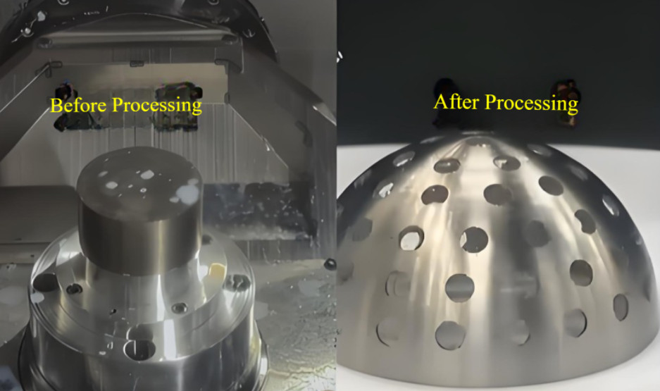
This document details a systematic method for machining external spherical surfaces using a turn-mill machining center equipped with Siemens five-axis functionality and a milling cutter. By integrating turning and milling processes, this approach achieves high contour accuracy and uniform surface quality. Validated through practical application, the method is efficient, precise, and reliable for producing spherical surfaces without requiring specialized equipment.
Introduction to Spherical Surface Machining
Machining spherical surfaces is a complex task due to the high demands for contour accuracy and surface roughness. Conventional machining methods, such as standalone turning or milling, often fall short of these requirements. Milling typically suffers from lower efficiency, reduced precision, and suboptimal surface finish, making it unsuitable for high-precision components. Turning, while more efficient and capable of better surface quality, is constrained by factors like machine tool precision, numerical control system limitations, and tool wear. These constraints make it challenging to consistently produce high-precision spherical surfaces using traditional turning alone.
The method described here utilizes a turn-mill machining center with a Siemens 840D numerical control system and five-axis Real-Time Control of Tool Point (RTCP) functionality. By combining turning and milling operations, this approach ensures uniform surface quality and high contour accuracy, offering a practical solution for machining external spherical surfaces without dedicated equipment.
Geometric Principle of Spherical Machining
The method is based on a key geometric principle: when a sphere intersects a plane, the resulting cross-section forms a circle. The radius of this circle depends on the distance between the plane and the sphere’s center. When the plane passes through the center, the circle’s radius equals the sphere’s radius, representing the largest possible cross-sectional diameter. Conversely, any circle can be formed by the intersection of a sphere with a radius equal to or greater than the circle’s radius.
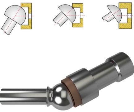
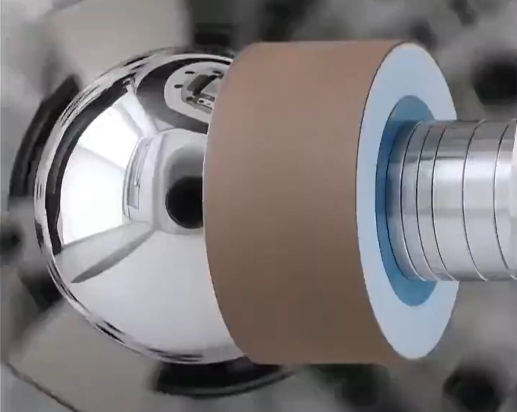
In this machining process, a milling cutter’s rotational motion creates a circular cutting path. By aligning this path with a rotating workpiece, the cutter shapes the workpiece into a spherical surface. The cutter’s rotation axis and the workpiece’s rotation axis are precisely controlled to ensure the cutter’s path intersects the workpiece at the desired spherical contour. This setup, combining the cutter’s circular motion with the workpiece’s rotation, produces the spherical geometry with high accuracy.
Data Calculation for Spherical Machining
Accurate calculation of machining parameters is essential for achieving the desired spherical geometry. Key parameters include the sphere’s radius, the milling cutter’s diameter, the cutter’s rotation angle, and the depth of cut. The following parameters and equations guide the calculation process:
- O: Center of the sphere.
- R: Radius of the sphere.
- A: Apex of the spherical surface.
- B: Termination point of the spherical surface.
- D: Diameter of the cross-sectional circle at the termination point.
- L1: Rotational axis of the workpiece.
- β: Angle between line OB and axis L1.
- L2: Rotational axis of the milling cutter, passing through the sphere’s center.
- α: Rotation angle of the milling cutter.
- H: Final depth of cut for the milling cutter.
The milling cutter’s rotation angle (α) is calculated as:
α = arcsin(D / (2R))
The milling cutter’s radius (r) and depth of cut (H) are derived as:
r = R * sin(α)
H = R * cos(α)
These calculations ensure the milling cutter is positioned correctly to produce the spherical contour within the specified machining range, maintaining precision and consistency.
Machining Equipment and Tools
The machining process employs a horizontal turn-mill machining center equipped with a Siemens 840D numerical control system. This system supports RTCP five-axis linkage and dual-channel functionality, enabling precise control of the tool’s position and orientation. The machine features a robust spindle for workpiece rotation and a milling head capable of five-axis motion, providing the flexibility and accuracy needed for complex spherical machining.
The tool used is a specialized milling cutter designed to generate a circular cutting path during rotation. The cutter’s diameter is adjustable to match the calculated dimensions based on the spherical surface’s specifications. This design ensures consistent material removal and a uniform surface finish across the spherical contour, critical for achieving high-quality results.
Step-by-Step Machining Method
The machining process integrates turning and milling operations in a structured sequence to produce the desired spherical surface. The steps are as follows:
- Initial Turning: Use a turning tool to rough-machine the workpiece into a near-spherical shape, leaving a machining allowance of 0.5–1 mm for subsequent milling.
- Tool Setup: Calculate the required milling cutter diameter based on the sphere’s dimensions and adjust the cutter to the specified size.
- Coordinate System Alignment: Set the workpiece coordinate system’s zero point at the sphere’s center. Rotate the milling cutter’s axis to the calculated angle (α) to align with the desired cutting path.
- Axis Alignment: Rotate the workpiece coordinate system so the Z-axis is parallel to the milling cutter’s rotational axis. Position the cutter’s axis to coincide with the rotated Z-axis and set the cutter at a safe height above the workpiece.
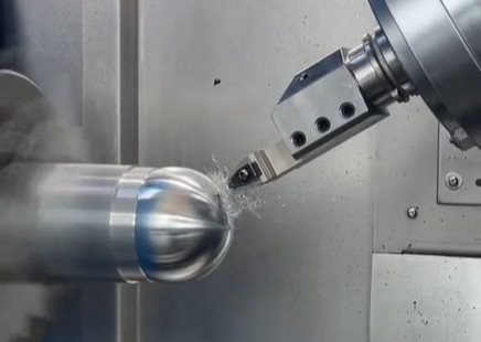
- Five-Axis Machining: Activate the five-axis RTCP function to enable linkage control. Start the milling cutter’s rotation and initiate slow workpiece rotation. Feed the cutter along the rotated Z-axis at a controlled cutting speed (e.g., 100 mm/min) until it reaches the calculated depth (H).
- Completion: After reaching the machining depth, ensure the workpiece rotates at least 360° to complete the spherical surface. Retract the cutter along the feed axis to its initial position.
This methodical approach ensures precise control over the cutter’s position and the workpiece’s rotation, resulting in a high-quality spherical surface with minimal deviation.
Sample CNC Program
The following CNC program illustrates the machining process using the Siemens 840D system. The program assumes a sphere radius (R) of 50 mm, a milling cutter rotation angle (α) of 45°, and a feed rate of 100 mm/min.
| Line | Code | Description |
|---|---|---|
| N1 | DIAMOF | Disable diameter programming |
| N2 | D0 | Select tool offset 0 |
| N3 | G17 | Select XY plane |
| N4 | G500 | Reset coordinate system |
| N5 | G00 X500 Y0 Z-600 | Rapid move to initial position |
| N6 | G94 | Feed per minute mode |
| N7 | G00 B45 | Rotate B-axis to 45° |
| N8 | M70 | Activate five-axis mode |
| N9 | TRAORI | Enable RTCP function |
| N10 | G55 | Select workpiece coordinate system |
| N11 | ROT Y225 | Rotate coordinate system by 225° around Y-axis |
| N12 | D1 | Select tool offset 1 |
| N13 | G00 X0 Y0 Z=R+10 | Rapid move to safe height (R + 10 mm) |
| N14 | M3 S1000 | Start spindle at 1000 RPM |
| N15 | G01 Z=H F100 | Feed to depth H at 100 mm/min |
| N16 | TRAFOOF | Disable RTCP function |
| N17 | G01 G91 C360 | Rotate workpiece 360° incrementally |
| N18 | TOFRAME | Reset coordinate system |
| N19 | G00 G90 Z=R+10 | Rapid retract to safe height |
| N20 | M5 | Stop spindle |
| N21 | TRAFOOF | Disable transformation |
| N22 | M30 | End program |
This program ensures precise execution of the machining steps, leveraging the Siemens system’s five-axis capabilities for accurate tool positioning and workpiece rotation.
Key Technical Considerations
To achieve optimal results, several technical considerations must be addressed during the machining process:
- Tool Path Accuracy: The milling cutter’s rotational trajectory must pass through the apex of the spherical surface, and its rotational center must align with the sphere’s center to ensure a complete and accurate spherical contour.
- Five-Axis Control: Activating the five-axis RTCP function allows precise control of the tool tip’s position, simplifying programming and enhancing machining accuracy.
- Workpiece Rotation: After reaching the machining depth, the workpiece must rotate at least 360° to ensure the entire spherical surface is machined uniformly.
- Tool Wear Management: Regular inspection and adjustment of the milling cutter are necessary to maintain consistent cutting performance and surface quality.
- Machine Calibration: The turn-mill machining center must be properly calibrated to ensure the accuracy of the five-axis linkage and coordinate system alignment.
Adhering to these considerations ensures the reliability and repeatability of the machining process, minimizing errors and achieving the desired surface quality.
Conclusion
The turn-mill machining method for spherical surfaces, utilizing a machining center with Siemens five-axis functionality, offers a robust and efficient solution for producing high-precision spherical components. By combining the strengths of turning and milling, this method achieves superior contour accuracy and surface quality without the need for specialized fixtures or equipment. The Siemens 840D system’s advanced features, such as RTCP and dual-channel functionality, simplify programming and enhance machining precision. This approach is particularly valuable for industries requiring high-precision spherical components, such as aerospace, automotive, and precision engineering, providing a practical and reliable alternative to traditional machining methods.