Stainless steel has advantages in corrosion resistance and wear resistance. The finished stainless steel products have high strength and toughness. They are widely used in mechanical equipment, molds and other fields. The stainless steel parts are key components of a certain mechanical equipment and have high accuracy requirements.
Stainless steel is difficult to cut. If the machability of high-quality carbon steel 45 is used as the reference standard (set to 1.0), the machability of austenitic stainless steel 304 is about 0.37. Stainless steel is an alloy steel with a chromium content of more than 12% or a nickel content of more than 8%. Its thermal conductivity is poor, and problems such as sticking knives and not easy to break chips during processing. Due to the poor thermal conductivity of stainless steel, its cutting temperature is higher than that of conventional steel cutting, up to 1000℃, and the parts are deformed during processing, making the accuracy difficult to control. During the actual cutting process, the heat carried by iron chips is at most Fz (feed per blade) on both sides. If the processed material has ideal thermal conductivity, the heat will be transmitted to the inside on the surface of Fz in a short time, taking away more machined heat. The degree of influence of different cutting parameters on residual stress is also different. From large to small, the cutting speed, cutting depth and feed amount, which is consistent with the influence of cutting parameters on cutting force and cutting temperature, indicating that the influence of cutting parameters on processing residual stress also works through mechanical and thermal effects. Therefore, setting reasonable cutting parameters has advantages in reducing part machining deformation. Stainless steel is welded with great deformation, and the weld area begins to shrink due to stress. Tensile residual stress is generated in the welding area, while the compression residual stress is subjected to the surrounding area of the welding area. Stainless steel materials face different degrees of shrinkage deformation. The welding area is large and the welding time is long, and the deformation of the welding workpiece increases accordingly.
Part design optimization and manufacturing process
Optimized design
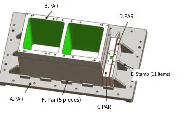
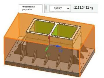
When designing a part processing model, considering its machining properties, the shape features of large parts are decomposed into several solid models. As shown in Figure 1, the decomposed components are A, B, C, D, E, and F, and the decomposed component features become simple. Compared with the materials required for the whole material preparation before decomposition and the materials required for the single-piece material preparation after decomposition, decomposition of the material can save 55.4% of the material, as shown in Figure 2. The processed parts are decomposed into single simple components, making the processing characteristics simpler, the processing difficulty is reduced, and the removal volume is also reduced. The production costs such as processing time and tool usage are reduced accordingly, which can reduce manufacturing costs and can also avoid a large number of electrode designs, electrode processing, discharge processing, etc. The design method of breaking the whole into pieces can reduce the processing cost of parts, shorten the processing cycle, and improve competitiveness.
Manufacturing process analysis
The processed parts can be decomposed into 2 main body components A, B and smaller components C, D, as well as multiple reinforcement ribs E, F, and more than 20 components are inlaid (see Figure 1). Difficulties in controlling the accuracy of the processing part: ① The main body component has large size, wall and large removal volume, which leads to long cutting time and large stress deformation, which can easily lead to excessive processing size differences; ② All inlays require welding connection seals, and the welding area is large, making it difficult to control deformation of the processed parts.

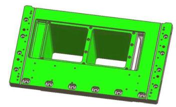
The equipment accuracy of the parts is required to be high. As shown in Figure 3, the plane degree of the maximum plane is required to be 0.05mm. The A component belongs to the large-scale board type. The single piece has a large deformation, and the deformation amount after welding is more difficult to estimate; the side walls of the two-way grooves of the component B component are 90° perpendicular, with a height of 425mm, and the verticality is required to be 0.05mm. It is necessary to meet the technical requirements of the drawings and the processing is difficult.
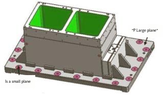
According to the above analysis, after the single component is finished, welding and inlaying cannot guarantee the tolerance requirements of the parts. Therefore, when the process is formulated, the single component is processed with a reserved margin, the pin (hole) positioning, screw (hole) tightening, and the assembly is integrated and the welding and inlaying cannot be guaranteed, and then the parts are finished to the required size. For parts with high accuracy requirements, the stress deformation of a single workpiece is released and eliminated through rough milling processing, air-cooling aging, and de-surplus processing. The surfaces that cannot be processed after assembly and the features with low accuracy requirements are processed in place in one go according to the requirements of the drawings, and then the components are assembled and welded into the whole component. Finally, the features with high accuracy requirements and reserved margin are fine-processed, as shown in Figure 4. The above-mentioned process methods can effectively control the processing accuracy. For the deformation surfaces that cannot be controlled, the P1 large plane shown in Figure 5 will deform after welding and cannot be controlled, but there are also plane requirements. On the premise of meeting the requirements for the use of mechanical parts, the design model is optimized, and the P2 small plane is increased according to the actual use needs. After welding and deformation, the P2 small plane is fine milled. This can not only make processing simple, but also ensure the processing technical requirements of the parts and reduce the processing cost.
Component processing
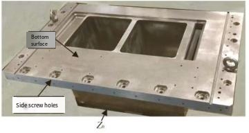
Component B machining
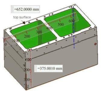
Component B is shown in Fig. 6 and is machined by efficient CNC. The component is rough milling cutting difficult workpiece, 70% of the material to be removed, and deep cavity machining, in order to reduce the difficulty of chip removal, choose horizontal CNC machine tool machining, according to the site conditions to determine the machining parameters shown in Table 1, the cutting efficiency of the tool to reach 40min / time, can reduce the frequency of operators to change the tool to improve processing efficiency. The processing steps are as follows.
(1) CNC machine rough milling height of 375mm, leaving a single side allowance of 2mm in the axial direction, the workpiece around the profile surface, the two through grooves are not processed for the time being.
(2) CNC machine rough milling around the shape of the surface, the two through the groove through, radial, axial allowance of 2mm/one side.
(3) Air-cooling aging treatment for 48h.
(4) CNC machine milling bottom surface, pin holes, screw holes, chamfering, bottom surface milling and A components for insertion.
(5) CNC machine around the side milling, processing of screw holes, pin holes, 648mm × 346mm × 82mm step surface is not processed for the time being, leaving the subsequent assembly after welding and then processing.
(6) Assembly, the clampman through the pin and hole, assembling components A, B, C, D and reinforcement, after welding.
Processing of component A

Component A belongs to thin plate type, as shown in Figure 7, large diameter milling cutter cutting processing extrusion generates a large force is easy to deform the component, in order to reduce the risk of deformation and improve the processing efficiency, the choice of D21mm milling cutter, rapid removal of residual material. The machining steps are as follows.
(1) CNC machine roughing front and bottom features, radial and axial leave a single side allowance of 2mm; processing is complete, the workpiece in the unconfined state, in the machine micrometer test flatness <2mm for qualified, can enter the next process.
(2) Air-cooled aging treatment for 48h.
(3) Detect the flatness <2mm is qualified, can enter the next process.
(4) CNC machine tool processing front, large plane milling axial margin 0.1mm (subsequent grinding to the final size); reinforcing the position of the slot, pin hole processing in place, around the side of the profile radial margin 0.5mm. processing of the bottom surface of the maximum profile of the workpiece four sides of the centre of the X0Y0, the bottom raised 0.1mm; 6 M10mm countersunk table threaded holes in place, the rest of the characteristics of the radial, axial Leave a margin of 1mm/unilateral processing.
(5) Grind the bottom surface to see the light, the front surface to the final size (0.1mm allowance left in the previous process), the top surface grinding to the final size, for and components B, C, D, E, F insertion.
(6) Assembly, clamps through the pins and holes, assembly of components A, B, C, D, E, F and reinforcement, after welding.
Processing of small components
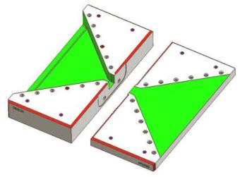
Small components C and D, as shown in Fig. 8, have low accuracy requirements and are machined directly to final size according to the drawings before the combination is burned. Reinforcement E, F drawings require free tolerance, multiple reinforcement components combined in a piece of material preparation, and then processed by wire cutting and shaped.
Assembly welding
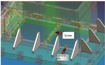
Large stainless steel parts welding process, due to the difficulty, must be predicted during the welding process possible deformation, in advance to take preventive measures to control. The process is to locate the welded parts, using the design of a number of pins (pin holes), screws (screw holes) to accurately assemble and fasten the parts, as shown in Figure 10, to ensure that the workpiece in the welding process to minimise displacement and the relative position of the workpiece and the workpiece to the workpiece remains unchanged. Welding process needs to master the welding parameters and methods, order, etc., in order to ensure that the deformation of stainless steel parts can be effectively controlled. Assembly welding after the combination of processing, as shown in Figure 11, the specific implementation steps are as follows.
(1) Detect the bottom surface flatness ≤ 0.5mm is qualified, can enter the next process.
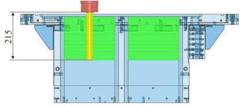
(2) CNC machine tool machining bottom surface, the maximum shape of component A, four sides of the centre of the X0Y0, the designated surface for the Z0, precision milling of the maximum shape, bottom plane, bottom surface features processing to the final size; precision milling of the through-slot 1/2 height to the final size, as shown in Figure 12. Because the total height of the two through grooves of the part is 425mm, R angle is 18mm, choose D32mm round nose cutter (carbide anti-vibration toolpost), the overhanging length after clamping is 215mm, machining 1/2 of the height of the groove to ensure the rigidity of the tool in order to ensure the final machining of the dimensional accuracy, after machining, using a micrometer to detect the through grooves have been finish milling the side of the perpendicularity, flatness ≤ 0.02mm is qualified. Processing of the top surface, sub-centre has been milled through the four sides of the groove for X0Y0, milling catching the remaining 1/2 height through the groove; processing of P2 shown in Figure 5 small plane, P1 large plane welding deformation is large, complex features, and there are no assembly requirements, no longer processed, machining is completed with a micrometer to detect has been milled through the groove sides of the two, perpendicularity, flatness ≤ 0.02mm is qualified. The introduction of process inspection in the production process of parts, parts of the key dimensions of the real-time inspection and confirmation of the parts are not processed in place or assembly of unreasonable parts to be corrected in a timely manner to ensure that the parts in the processing of the next machine to achieve the requirements of the qualified.
(3) CNC finish machining the threaded holes around the side of component A and the 82mm steps and threaded holes of component B.
(4) 600# sandpaper polishing the bottom large plane, two through grooves and bottom surface features, remove CNC milling lines.
Effectiveness verification
Surface roughness and dimensional accuracy are two important parameters in the quality evaluation index, these two parameters from the surface effect, geometric accuracy to reflect the good or bad parts manufacturing. Through the above machining process and batch parts processing verification, the final size, roughness detection data have reached the technical requirements of the drawings, especially the most difficult to control the bottom large plane shown in Figure 11, flatness detection values are ≤ 0.023mm, Figure 12 shows the two through the groove of the four sides of the flatness and perpendicularity <0.05mm. from the dimensional inspection data, it can be seen that this type of stainless steel parts, through the above process, can control the machining, burnishing and welding. process, can control the deformation generated by processing, welding, to ensure the processing quality.
Large stainless steel parts processing using the decomposition method, can effectively reduce the processing difficulty of the parts and reduce the processing deformation, components to take the pin hole (nail) positioning and screw holes (nails) fastening measures to ensure the accuracy of assembly and reduce the deformation of the welding; cutting process, reduce the speed of cutting, depth of cut, feed per edge can ensure that stainless steel cutting smoothly; decomposition of the components of single piece When processing, leave the appropriate margin, assembly and welding after combining and then finishing, can ensure the accuracy of the key dimensions.

High-Precision Five-Axis Machining for Large Stainless Steel Parts
KeSu's five-axis machining solution is tailored for stainless steel parts, integrating advanced CNC technology and extensive industry expertise to effortlessly handle complex geometries and high-precision requirements. From aerospace and medical devices to automotive manufacturing, we ensure each part boasts impeccable surface finish, precise dimensions, and reliable performance. With intelligent machining path optimization, we reduce production cycles and costs while maintaining exceptional quality. Choose us, and your stainless steel parts will seamlessly transition from design to finished product, driving your project’s success!
Conclusion
The processing of large stainless steel parts, characterized by high strength, toughness, and poor machinability, presents significant challenges in controlling deformation and ensuring precision. By adopting a decomposition design approach, the complex part is broken down into simpler components (A, B, C, D, E, F), reducing material usage by 55.4%, simplifying machining characteristics, and lowering manufacturing costs. The optimized manufacturing process, incorporating rough milling, air-cooling aging, precise assembly with pin and screw fastening, and strategic margin reservation, effectively mitigates stress-induced deformation from cutting and welding. Critical machining steps, such as CNC milling with carefully selected parameters and tools, ensure high accuracy, with flatness and perpendicularity meeting stringent requirements (≤0.05mm and ≤0.02mm, respectively). Post-welding finishing and process inspection further guarantee dimensional accuracy and surface quality. This integrated approach of design optimization, controlled machining, and precise assembly successfully addresses the challenges of stainless steel processing, ensuring high precision, reduced deformation, and enhanced manufacturing efficiency for large-scale components.
FAQ
Why is stainless steel difficult to machine compared to other materials?
Stainless steel, such as austenitic stainless steel 304, has a machinability rating of approximately 0.37 compared to high-quality carbon steel 45 (rated at 1.0). Its high strength, toughness, and poor thermal conductivity lead to issues like tool sticking, difficulty in chip breaking, and high cutting temperatures (up to 1000°C), which cause deformation and make precision control challenging.
How does the decomposition design method benefit the manufacturing of large stainless steel parts?
The decomposition design method breaks down large parts into simpler components (e.g., A, B, C, D, E, F), reducing material usage by 55.4%, simplifying machining features, lowering processing difficulty, and decreasing production costs. It minimizes the need for complex electrode designs and reduces processing time, enhancing competitiveness.
What are the main challenges in maintaining precision during stainless steel part processing?
Key challenges include: large component size and material removal (e.g., 70% for component B), leading to long cutting times and stress-induced deformation; and large welding areas causing shrinkage, generating tensile residual stress in the weld zone and compressive stress in surrounding areas, making it difficult to meet tight tolerances (e.g., 0.05mm flatness and perpendicularity).
What measures ensure welding accuracy and minimize deformation?
Welding accuracy is ensured by using pin and screw holes for precise alignment, controlling welding parameters and sequence, and post-welding CNC finishing of critical surfaces (e.g., through grooves to 0.02mm flatness/perpendicularity) and polishing with 600# sandpaper to remove milling lines.
How is the final quality of the parts verified?
Quality is verified through dimensional and surface roughness inspections, achieving bottom large plane flatness ≤0.023mm and through groove flatness/perpendicularity ≤0.05mm (side surfaces ≤0.02mm). Real-time process inspections ensure timely corrections, guaranteeing compliance with technical requirements.