Micro-arc oxidation (MAO), also known as plasma electrolytic oxidation (PEO), is a surface treatment technology widely applied to aluminum, magnesium, and titanium alloys to enhance corrosion resistance, wear resistance, and insulation properties. In centrifugal impellers, MAO coatings are critical for durability in harsh environments, such as marine or chemical processing applications. However, coating peeling remains a significant issue, compromising performance and longevity. This article provides a systematic, technical approach to identifying the causes of MAO coating peeling on centrifugal impellers and offers practical solutions supported by detailed parameters and processes.
Understanding Micro-Arc Oxidation and Its Application
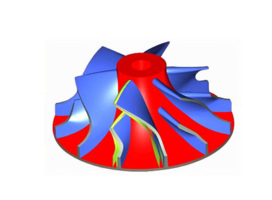
MAO is an electrochemical process that generates a ceramic oxide layer on the surface of valve metals through high-voltage arc discharges in an electrolyte solution. The resulting coating is composed primarily of metal oxides, offering superior hardness, adhesion, and corrosion resistance compared to traditional anodizing. For centrifugal impellers, typically made from aluminum alloys (e.g., 5083 or 6061), MAO coatings protect against erosion and corrosion caused by high-speed fluid flow and aggressive media.
The MAO process involves immersing the impeller in an alkaline electrolyte (e.g., sodium silicate or potassium hydroxide solution) and applying a high-voltage current (typically 400–600 V) to induce micro-arc discharges. These discharges create a ceramic layer with a thickness of 10–100 µm, depending on process parameters. However, improper control of these parameters or material preparation can lead to coating defects, including peeling.
Causes of MAO Coating Peeling
Coating peeling occurs when the MAO layer detaches from the substrate, reducing the impeller’s protective capabilities. Several factors contribute to this issue, each requiring specific mitigation strategies.
Substrate Surface Preparation Issues
Inadequate surface preparation is a primary cause of poor coating adhesion. Residual contaminants, such as oils, oxides, or machining residues, create weak interfaces between the substrate and the MAO layer. For centrifugal impellers, complex geometries with curved blades and tight crevices can trap contaminants, exacerbating adhesion problems.
Electrolyte Composition and Stability
The electrolyte’s chemical composition directly affects coating quality. Common electrolytes include sodium silicate (5–20 g/L), sodium hydroxide (1–5 g/L), and additives like sodium aluminate (2–10 g/L). Imbalances in concentration or degradation of the electrolyte over time can lead to uneven coating formation or porous structures, increasing the likelihood of peeling under mechanical or thermal stress.
Process Parameter Variations
MAO process parameters, such as voltage, current density, and duty cycle, must be precisely controlled. For example, a voltage range of 450–550 V and a current density of 5–15 A/dm² are typical for aluminum alloys. Excessive voltage can cause overheating, leading to microcracks, while insufficient voltage may result in incomplete coating formation. Variations in pulse frequency (100–1000 Hz) or duty cycle (10–50%) can also disrupt coating uniformity.
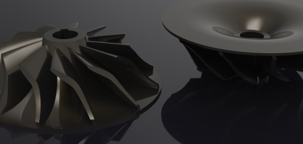
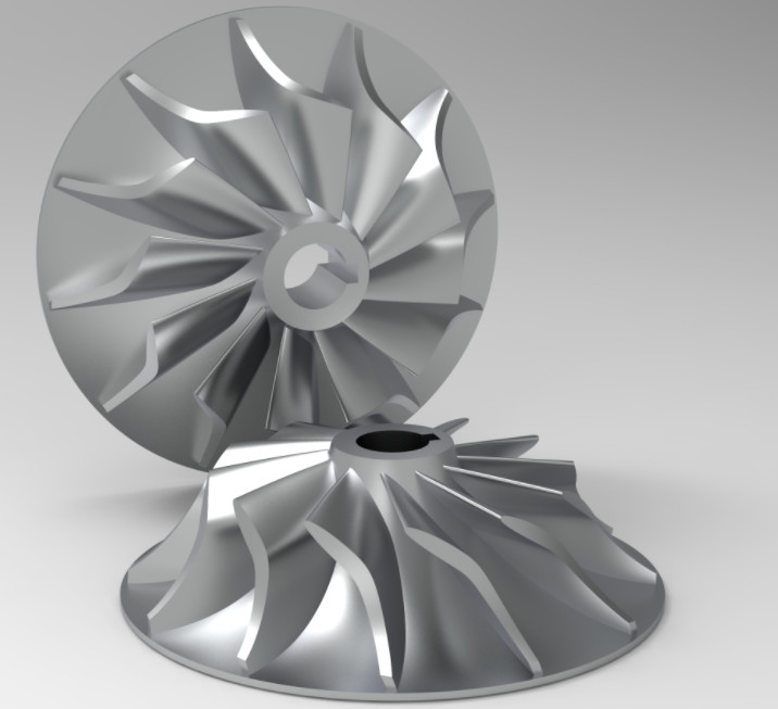
Impeller Geometry and Coating Uniformity
The complex geometry of centrifugal impellers, with narrow channels and curved surfaces, poses challenges for uniform coating deposition. Areas with high curvature or limited electrolyte access may experience weak or incomplete coating growth, creating stress concentration points prone to peeling.
Post-Processing and Handling
Improper handling or post-processing, such as excessive mechanical stress during assembly or exposure to corrosive environments before sealing, can damage the MAO coating. For instance, impacts during installation can initiate microcracks, leading to eventual peeling.
Solutions to Prevent MAO Coating Peeling
Addressing coating peeling requires a systematic approach, combining optimized material preparation, process control, and post-treatment techniques. Below are detailed solutions tailored to centrifugal impellers.
Optimized Surface Preparation
Effective surface preparation ensures strong adhesion between the substrate and the MAO coating. The following steps are recommended:
- Degreasing: Use an alkaline degreasing solution (e.g., 5% NaOH at 60°C for 5–10 minutes) to remove oils and organic residues.
- Acid Etching: Apply a solution of 10% HNO₃ or 5% HF for 1–2 minutes to remove surface oxides and create a micro-roughened surface for better adhesion.
- Ultrasonic Cleaning: Use deionized water with ultrasonic agitation (40 kHz, 5 minutes) to clean complex impeller geometries, ensuring no residues remain in crevices.
- Drying: Dry the impeller at 80–100°C for 10 minutes to eliminate moisture, preventing interference with the MAO process.
Verification of surface cleanliness using a water-break test ensures no hydrophobic contaminants remain.
Electrolyte Optimization
Maintaining a stable and effective electrolyte composition is critical. Key considerations include:
- Composition Control: Use a silicate-based electrolyte with 10 g/L sodium silicate, 2 g/L NaOH, and 5 g/L sodium aluminate. Monitor pH (10–12) and conductivity (10–20 mS/cm) daily.
- Temperature Regulation: Keep the electrolyte at 20–30°C using a cooling system to prevent overheating, which can degrade coating quality.
- Additives: Incorporate 1–3 g/L of sodium phosphate to enhance coating density and reduce porosity.
- Filtration: Use a 5 µm filter to remove particulate contaminants from the electrolyte, ensuring consistent arc discharge behavior.
Regular electrolyte replacement (every 50–100 hours of operation) prevents degradation and maintains coating quality.
Precise Process Parameter Control
Optimizing MAO process parameters minimizes defects and enhances coating adhesion. The following parameters are recommended for aluminum alloy impellers:
| Parameter | Recommended Range | Purpose |
|---|---|---|
| Voltage | 450–550 V | Ensures stable arc discharge and uniform coating growth |
| Current Density | 8–12 A/dm² | Balances coating thickness and minimizes overheating |
| Pulse Frequency | 200–500 Hz | Controls arc size and coating porosity |
| Duty Cycle | 20–40% | Reduces thermal stress and microcrack formation |
| Processing Time | 30–60 minutes | Achieves 20–50 µm coating thickness |
Real-time monitoring of voltage and current using a programmable power supply ensures consistency. A gradual ramp-up of voltage (50 V/min) prevents initial overheating.
Addressing Geometric Challenges
To ensure uniform coating on complex impeller geometries, the following techniques are effective:
- Auxiliary Electrodes: Place stainless steel auxiliary electrodes near high-curvature areas to enhance electric field distribution and coating uniformity.
- Electrolyte Flow: Use a circulation pump (flow rate: 10–20 L/min) to ensure fresh electrolyte reaches all surfaces, preventing localized depletion.
- Rotational Jigs: Rotate the impeller at 5–10 rpm during MAO to expose all surfaces evenly to the electric field.
Finite element analysis (FEA) can be used to simulate electric field distribution and optimize electrode placement before processing.
Post-Processing and Sealing
Post-processing enhances coating durability and prevents peeling. Recommended steps include:
- Sealing: Apply a sol-gel sealant (e.g., silica-based) or epoxy resin (1–2 µm thickness) to fill micropores and improve corrosion resistance.
- Heat Treatment: Anneal the coated impeller at 150–200°C for 1 hour to relieve residual stresses and enhance coating toughness.
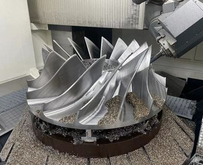
- Handling Protocols: Use padded fixtures during assembly to avoid mechanical damage to the coating.
Corrosion testing (e.g., ASTM B117 salt spray test) verifies the effectiveness of sealing, targeting a minimum of 1000 hours without coating degradation.
Quality Control and Testing
Rigorous quality control ensures the reliability of MAO coatings. Key testing methods include:
- Adhesion Testing: Perform a cross-cut test (ASTM D3359) to evaluate coating adhesion, targeting a rating of 4B or higher.
- Thickness Measurement: Use an eddy current gauge to confirm coating thickness (20–50 µm) across all impeller surfaces.
- Microstructure Analysis: Examine cross-sections using scanning electron microscopy (SEM) to detect porosity or microcracks.
- Corrosion Resistance: Conduct a salt spray test (ASTM B117) or electrochemical impedance spectroscopy (EIS) to assess coating performance in corrosive environments.
Non-destructive testing (NDT) methods, such as ultrasonic inspection, can detect subsurface defects without damaging the impeller.
Case Study: Application Example
A centrifugal impeller made from 6061 aluminum alloy, used in a marine pump, experienced coating peeling after MAO treatment. The initial process used a 400 V voltage, 15 g/L sodium silicate electrolyte, and no ultrasonic cleaning. After implementing the following changes, peeling was eliminated:
- Surface preparation with 5% NaOH degreasing and 10% HNO₃ etching.
- Electrolyte with 10 g/L Na silicate, 2 g/L NaOH, and 3 g/L Na phosphate, maintained at 25°C.
- Process parameters: 500 V, 10 A/dm², 300 Hz, 30% duty cycle, 45 minutes.
- Auxiliary electrodes and a 15 L/min electrolyte flow to ensure uniform coating.
- Post-treatment with silica sol-gel sealing and 150°C annealing.
Post-treatment testing showed a coating thickness of 30 µm, adhesion rating of 5/10, and no peeling after 1500 hours of salt spray exposure.
Summary
MAO coating peeling on centrifugal impellers can be effectively addressed through optimized surface preparation, electrolyte management, process parameter control, and post-processing. By implementing the solutions outlined, manufacturers can achieve durable, high-performance coatings that withstand harsh operating conditions. Regular quality control and tailored process adjustments ensure consistent results, enhancing the reliability of MAO-treated impellers in demanding applications.