Impellers are critical components in turbomachinery, requiring high precision to ensure aerodynamic performance and mechanical reliability. Achieving a concentricity of 0.005mm is a stringent requirement that demands meticulous planning, advanced equipment, and precise execution in five-axis machining. This guide provides a systematic approach to optimize impeller concentricity, focusing on machine setup, tool selection, programming strategies, machining processes, and inspection methods. The content is structured to deliver technical insights based on established practices, ensuring clarity and reliability for engineers and machinists.
Machine Setup and Calibration
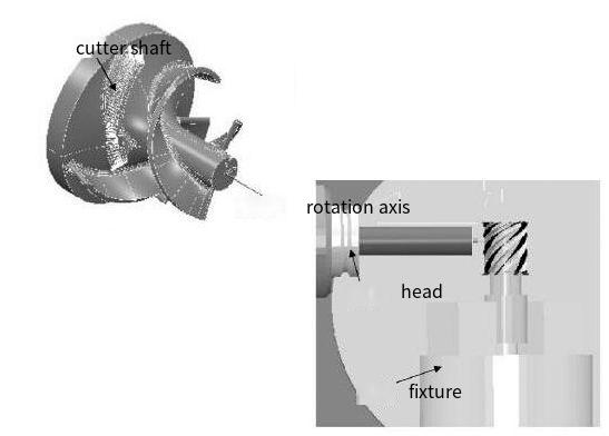
Five-axis machining centers offer the flexibility to machine complex geometries like impellers by controlling three linear axes (X, Y, Z) and two rotational axes (A, B or C). Proper machine setup is foundational to achieving 0.005mm concentricity.
- Machine Stability: Ensure the machine is installed on a vibration-free foundation. Use precision leveling tools to align the machine bed within 0.01mm/m. Regular maintenance of spindle bearings and guideways minimizes thermal expansion and mechanical drift.
- Axis Calibration: Calibrate all five axes using laser interferometry or ball-bar testing to verify positioning accuracy within ±0.002mm. Check rotary axis alignment to ensure the center of rotation aligns with the workpiece datum.
- Workholding: Use high-precision fixtures, such as hydraulic or pneumatic chucks, to secure the impeller blank. The fixture must provide uniform clamping force to avoid distortion, with runout not exceeding 0.003mm. For example, a custom-designed collet chuck with a repeatability of 0.002mm is ideal for small impellers.
- Thermal Compensation: Implement thermal compensation systems to counteract spindle growth and machine frame expansion. Maintain a controlled shop environment at 20±1°C to stabilize material and machine behavior.
Before machining, perform a test cut on a reference workpiece to confirm setup accuracy. Measure the test piece using a coordinate measuring machine (CMM) to validate concentricity and positional tolerances.
Tool Selection and Management
Tool selection directly impacts surface quality, dimensional accuracy, and concentricity. Impellers, with their thin blades and complex geometries, require specialized tools optimized for five-axis machining.
- Tool Material: Use solid carbide or polycrystalline diamond (PCD) tools for high-temperature alloys like Inconel or titanium, common in impellers. Carbide tools with TiAlN or AlCrN coatings reduce wear and improve chip evacuation.
- Tool Geometry: Select tapered ball-end mills for roughing and finishing blade surfaces. For example, a 6mm diameter ball-end mill with a 3° taper angle minimizes deflection while accessing narrow channels. For hub machining, use flat-end mills with corner radii of 0.5mm to ensure strength.
- Tool Length and Overhang: Minimize tool overhang to reduce vibration. A tool length-to-diameter ratio of 3:1 is recommended for stability. For deep channels, use extended-reach tools with reinforced shanks, ensuring deflection does not exceed 0.001mm.
- Tool Holder: Employ high-precision tool holders, such as HSK-63A or BT-40 with shrink-fit clamping, to achieve runout below 0.002mm. Side-lock holders are preferred over collet chucks to prevent tool slippage under high cutting forces.
Implement a tool management system to track wear and replace tools before they compromise accuracy. Use presetting devices to measure tool dimensions offline, ensuring runout and length tolerances are within ±0.001mm. During machining, monitor tool condition with in-process sensors to detect wear or breakage.
Programming Strategies for Five-Axis Machining
Effective programming is critical to achieving 0.005mm concentricity. Five-axis machining allows simultaneous control of tool orientation and position, enabling precise tool paths for complex impeller geometries.
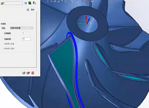
- CAD/CAM Software: Use advanced CAM software like Siemens NX, PowerMill, or HyperMill, which support five-axis tool path generation. Import a high-fidelity CAD model of the impeller, ensuring surface definitions use NURBS (Non-Uniform Rational B-Splines) for smooth tool paths.
- Roughing Tool Paths: Apply adaptive roughing strategies to remove material efficiently while minimizing tool deflection. Use trochoidal milling with a step-over of 20-30% of tool diameter and a depth of cut of 0.5-1.0mm. Maintain a constant chip load of 0.02-0.05mm/tooth to reduce vibration.
- Semi-Finishing: Use swarf milling or morph-between-curves strategies to create uniform stock allowances of 0.1-0.2mm on blade surfaces. Control tool axis tilt to avoid interference with adjacent blades, typically maintaining a 5-10° lead angle.
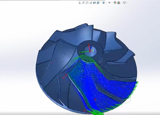
- Finishing Tool Paths: Employ parallel-to-surface or flow-line finishing with a step-over of 0.01-0.02mm to achieve surface roughness Ra 0.4µm. Use constant scallop height control to ensure uniform surface finish. For hub surfaces, apply spiral tool paths with a 0.005mm step-over to minimize concentricity errors.
- Collision Avoidance: Simulate tool paths in CAM software to detect collisions between the tool, holder, and impeller. Adjust tool axis vectors to maintain a minimum clearance of 0.5mm from adjacent blades.
Post-process the tool paths using machine-specific post-processors to ensure compatibility with the CNC controller (e.g., Siemens 840D or Fanuc 31i). Verify programs with a virtual machine simulation to confirm kinematic accuracy and concentricity compliance.
Machining Process Execution
The machining process involves roughing, semi-finishing, and finishing stages, each tailored to maintain concentricity within 0.005mm. Execution requires precise control of cutting parameters and in-process monitoring.
| Stage | Cutting Parameters | Tool Type | Objective |
|---|---|---|---|
| Roughing | Spindle Speed: 8000-12000 RPM Feed Rate: 1000-2000 mm/min Depth of Cut: 0.5-1.0mm | Tapered Bull-Nose Mill (Ø10mm) | Remove 80-90% of material, maintain stock allowance of 0.5mm |
| Semi-Finishing | Spindle Speed: 12000-15000 RPM Feed Rate: 800-1200 mm/min Depth of Cut: 0.1-0.2mm | Ball-End Mill (Ø6mm) | Uniform stock allowance of 0.1mm, prepare for finishing |
| Finishing | Spindle Speed: 15000-18000 RPM Feed Rate: 500-800 mm/min Depth of Cut: 0.01-0.02mm | Ball-End Mill (Ø4mm) | Achieve final geometry, surface finish Ra 0.4µm |
Process Details:
- Roughing: Divide the impeller into sub-regions (hub, blades, channels) to optimize material removal. Use regional milling to minimize tool path length and maintain uniform stock. Monitor spindle load to prevent tool overload, keeping power consumption below 80% of rated capacity.
- Semi-Finishing: Focus on blade surfaces to ensure consistent stock for finishing. Use in-process probing to measure stock allowance, adjusting tool paths if deviations exceed 0.02mm. Maintain coolant pressure at 50-70 bar to improve chip evacuation and reduce thermal distortion.
- Finishing: Apply high-speed machining techniques with minimal depth of cut to reduce cutting forces. Use climb milling to improve surface finish and minimize tool marks. Perform finishing in a single setup to avoid repositioning errors.
Throughout machining, use adaptive feed rate control to adjust speeds based on material resistance, ensuring consistent cutting forces. Regularly inspect the workpiece with on-machine probes to verify critical dimensions, correcting any deviations before proceeding to the next stage.
Inspection and Quality Control
Verifying concentricity to 0.005mm requires advanced metrology and rigorous quality control procedures.
- In-Process Inspection: Use touch probes integrated into the five-axis machine to measure blade and hub datums during machining. Set probe accuracy to ±0.001mm and calibrate before each use. Check concentricity after semi-finishing to identify errors early.
- Final Inspection: Employ a CMM with a scanning probe (e.g., Zeiss REVO) to measure the impeller’s geometry. Define concentricity relative to the hub’s central axis, using a least-squares fit to calculate deviation. Ensure measurement uncertainty is below 0.001mm.
- Surface Finish: Use a profilometer to verify surface roughness (Ra 0.4µm). Measure multiple points on blade surfaces and hub to confirm uniformity.
- Dynamic Balancing: Perform dynamic balancing on a high-speed balancer (e.g., Schenck CAB 920) to achieve G1 balance quality. Correct imbalances to ensure rotational stability, which indirectly supports concentricity.
Document all measurements in a quality control report, including concentricity, surface finish, and dimensional tolerances. If deviations exceed 0.005mm, analyze root causes (e.g., tool wear, fixture misalignment) and adjust the process accordingly.
Best Practices for Consistent Results
To sustain 0.005mm concentricity in production, adopt the following practices:
- Standardized Procedures: Develop detailed work instructions for setup, programming, and inspection. Train operators to follow these consistently.
- Fixture Design: Use modular fixtures to accommodate different impeller sizes while maintaining repeatability. Incorporate datum locators to simplify alignment.
- Tool Path Optimization: Regularly review CAM programs to reduce machining time without compromising accuracy. Use historical data to refine step-over and feed rates.
- Machine Maintenance: Schedule preventive maintenance every 500 hours of operation, focusing on spindle, axes, and coolant systems.
- Data Tracking: Implement a manufacturing execution system (MES) to monitor process parameters and quality metrics in real-time.
By integrating these practices, manufacturers can achieve repeatable concentricity of 0.005mm, ensuring impeller performance and reliability in demanding applications.
Conclusion
Optimizing impeller concentricity to 0.005mm using five-axis machining requires a holistic approach encompassing machine setup, tool selection, programming, machining execution, and inspection. By adhering to precise calibration, selecting appropriate tools, employing advanced CAM strategies, controlling cutting parameters, and implementing rigorous quality checks, manufacturers can meet this tight tolerance. The outlined methods, grounded in technical expertise, provide a reliable framework for producing high-precision impellers, ensuring operational efficiency and product quality in turbomachinery applications.