Micro-arc oxidation (MAO), also known as plasma electrolytic oxidation, is a surface treatment technique used to form ceramic coatings on high-temperature alloy impellers, particularly those made from titanium, aluminum, or magnesium alloys. These coatings enhance wear resistance, corrosion resistance, and thermal stability, critical for impellers operating in demanding environments like aerospace and industrial turbines. This guide outlines a systematic approach to optimizing the MAO process, focusing on technical parameters and procedural steps to achieve high-quality coatings. The content is structured to provide a clear, experience-based, and professional methodology, supported by precise parameters where applicable, to ensure reliable outcomes.
1. Selection and Preparation of High-Temperature Alloy Substrate
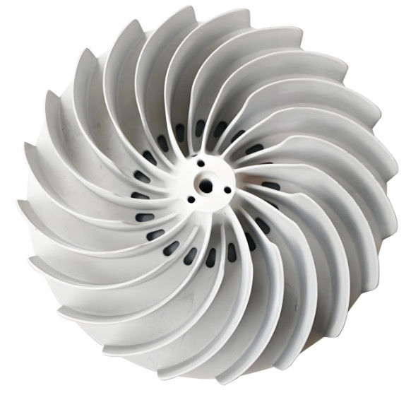
The first step in optimizing the MAO process is selecting and preparing the high-temperature alloy substrate, typically titanium or nickel-based alloys for impellers due to their high strength-to-weight ratio and thermal resistance. The substrate's surface condition significantly influences coating adhesion and quality. Proper preparation ensures a uniform coating and minimizes defects.
Substrate Selection: Titanium alloys (e.g., Ti-6Al-4V) are commonly used for impellers due to their excellent mechanical properties and compatibility with MAO. The alloy composition must be verified to ensure it supports the formation of a stable oxide layer. Nickel-based alloys may require additional pre-treatments due to their complex microstructure.
Surface Preparation:
- Cleaning: Degrease the impeller surface using acetone or ethanol to remove organic contaminants. Ultrasonic cleaning for 10–15 minutes at 40 kHz ensures thorough removal of oils and residues.
- Mechanical Polishing: Polish the surface to a roughness of Ra 0.2–0.4 μm using abrasive papers (e.g., 800–1200 grit) to enhance coating adhesion.
- Chemical Etching: Etch the surface with a solution of 10% HF and 30% HNO₃ for 30–60 seconds to remove oxide layers and surface impurities, followed by rinsing with deionized water.
- Drying: Dry the impeller at 60°C for 30 minutes to eliminate moisture, preventing interference during MAO.
Considerations: Inconsistent surface preparation can lead to uneven coating thickness or poor adhesion. Ensure uniform polishing and etching across complex impeller geometries to avoid localized defects.
2. Electrolyte Composition Optimization
The electrolyte is a critical factor in MAO, as it influences the plasma discharge characteristics and coating properties. Optimizing the electrolyte composition involves selecting appropriate chemicals and concentrations to promote the formation of a dense, uniform ceramic layer with desired properties like hardness and corrosion resistance.
Electrolyte Components:
- Base Electrolyte: Sodium silicate (Na₂SiO₃) at 8–15 g/L is commonly used to facilitate oxide layer formation. It provides silicate ions that contribute to the ceramic coating's structure.
- Additives: Potassium hydroxide (KOH, 2–5 g/L) adjusts pH (typically 11–13) to stabilize plasma discharges. Sodium aluminate (NaAlO₂, 1–3 g/L) enhances coating density by incorporating aluminum oxide into the coating.
- Stabilizers: Sodium fluoride (NaF, 0.5–1 g/L) improves coating uniformity by reducing arc intensity and preventing excessive sparking.
Optimization Process:
- Conduct small-scale trials to test electrolyte combinations. For titanium alloys, a combination of 10 g/L Na₂SiO₃, 3 g/L KOH, and 0.8 g/L NaF is effective for producing a dense coating.
- Measure electrolyte conductivity (typically 10–20 mS/cm) to ensure stable plasma discharges. Adjust concentrations if conductivity deviates significantly.
- Maintain electrolyte temperature at 20–30°C using a cooling system to prevent overheating, which can alter coating microstructure.
Testing and Validation: Analyze coating properties (e.g., thickness, hardness) using SEM and micro-hardness testers. Adjust electrolyte composition based on results to achieve a coating thickness of 20–50 μm and hardness of 800–1200 HV.
3. Electrical Parameter Adjustment
Electrical parameters, including voltage, current density, frequency, and duty cycle, directly affect the energy input during MAO, influencing coating thickness, porosity, and phase composition. Optimizing these parameters ensures a balance between coating quality and energy efficiency.
Key Parameters:
| Parameter | Recommended Range | Effect on Coating |
|---|---|---|
| Positive Voltage | 350–450 V | Higher voltages increase coating thickness but may cause excessive porosity. |
| Current Density | 5–15 A/dm² | Higher densities enhances growth rate but risks surface burning. |
| Frequency | 500–1000 Hz | Higher frequencies reduce pore size, improving coating density. |
| Duty Cycle | 40–60% | Optimizes energy input, balancing coating growth and uniformity. |
Optimization Steps:
- Initial Setup: Start with a baseline of 400 V, 10 A/dm², 600 Hz, and 50% duty cycle for titanium alloy impellers.
- Incremental Adjustments: Increase voltage in 10 V steps to monitor coating thickness (target 30–50 μm). Adjust frequency in 50 Hz increments to minimize pore size (target <3 μm).
- Monitoring: Use an oscilloscope to observe discharge characteristics. Stable, uniform sparks indicate optimal parameters.
- Validation: Test coating properties after each adjustment. For example, a coating formed at 400 V, 550 Hz, and 60% duty cycle achieved a porosity of 12% and hardness of 1000 HV.
Considerations: Excessive voltage or current density can lead to surface burning or cracking, particularly on complex impeller surfaces. Regular calibration of power supply equipment is essential for consistency.
4. Process Duration and Temperature Control
The duration of the MAO process and temperature control are critical for achieving a uniform coating without thermal damage to the substrate or coating. Proper management of these factors ensures optimal coating growth and structural integrity.
Process Duration:
- Typical Range: 15–30 minutes, depending on desired coating thickness. For a 30 μm coating on titanium impellers, 20–25 minutes is sufficient.
- Optimization: Conduct trials at 5-minute intervals to determine the minimum time required for target thickness. Excessive duration increases porosity and energy consumption.
Temperature Control:
- Electrolyte Temperature: Maintain at 20–30°C using a cooling system to prevent overheating, which can lead to irregular coating growth.
- Substrate Monitoring: Use infrared thermography to monitor impeller surface temperature, keeping it below 100°C to avoid thermal stress.
Validation: Measure coating thickness and uniformity using cross-sectional SEM. A well-controlled process yields a coating with a uniform thickness of 30–50 μm and minimal defects.
5. Post-Treatment and Quality Assessment
Post-treatment and quality assessment ensure the MAO coating meets performance requirements for high-temperature alloy impellers. Post-treatments can enhance coating properties, while rigorous testing confirms reliability.
Post-Treatment Options:
- Sealing: Apply a sealing layer (e.g., epoxy or silicate-based sealant) to fill micropores, reducing porosity to <5% and enhancing corrosion resistance.
- Annealing: Heat-treat the coating at 200–300°C for 1–2 hours to relieve residual stresses and improve coating toughness.
- Polishing: Lightly polish the coating to achieve a surface roughness of Ra 0.1–0.2 μm, improving wear resistance for impeller applications.
Quality Assessment:
| Test Method | Parameter | Target Value |
|---|---|---|
| SEM | Coating Thickness | 20–50 μm |
| Micro-Hardness Tester | Hardness | 800–1200 HV |
| XRD | Phase Composition | Predominantly anatase TiO₂ or Al₂O₃ |
| Salt Spray Test | Corrosion Resistance | No pitting after 1000 hours |
Procedure: Conduct SEM and XRD to analyze microstructure and phase composition. Perform micro-hardness tests at multiple points to ensure uniformity. Conduct salt spray tests to verify corrosion resistance, particularly for impellers in marine or high-humidity environments.
6. Process Integration and Scale-Up
Integrating the optimized MAO process into production and scaling it for industrial applications requires careful planning to maintain consistency across multiple impellers. This step ensures the process is repeatable and cost-effective.
Integration Steps:
- Equipment Setup: Use a high-capacity MAO system with automated control for voltage, current, and electrolyte flow. Ensure the system accommodates impeller sizes (e.g., 100–500 mm diameter).
- Batch Processing: Develop fixtures to hold multiple impellers, ensuring uniform electrolyte flow and electric field distribution.
- Quality Control: Implement in-line monitoring of electrical parameters and electrolyte conditions. Use statistical process control to track coating thickness and hardness variations.
Scale-Up Considerations: For large impellers, increase electrolyte volume and cooling capacity to maintain temperature stability. Validate the process on a small batch before full-scale production to ensure consistency.
Conclusion
Optimizing the micro-arc oxidation process for high-temperature alloy impellers involves a systematic approach encompassing substrate preparation, electrolyte optimization, electrical parameter adjustment, process duration control, post-treatment, and production integration. By carefully controlling parameters such as voltage (350–450 V), frequency (500–1000 Hz), and electrolyte composition (e.g., 10 g/L Na₂SiO₃), a dense, uniform ceramic coating with a thickness of 20–50 μm and hardness of 800–1200 HV can be achieved. Rigorous quality assessment ensures the coating meets performance requirements for wear and corrosion resistance. This methodology, grounded in technical precision and systematic execution, provides a reliable framework for producing high-quality MAO coatings on impellers for demanding applications.