Impellers, critical components in pumps, turbines, and compressors, require high contour accuracy to ensure aerodynamic performance and mechanical reliability. Achieving a contour accuracy of 0.006mm using five-axis machining demands precise control over toolpaths, machine dynamics, and error compensation. This guide provides a systematic approach to optimizing impeller machining, focusing on technical processes and parameters derived from established practices.
Understanding Impeller Geometry and Machining Requirements
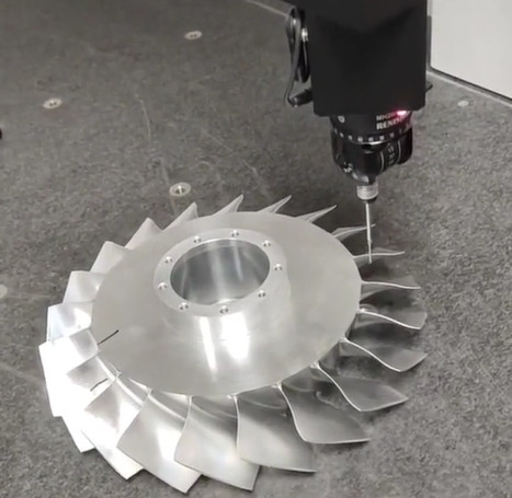
Impellers feature complex, free-form surfaces, often with thin, twisted blades and narrow channels. These geometries necessitate five-axis machining to access all surfaces in a single setup, minimizing repositioning errors. Contour accuracy of 0.006mm requires addressing geometric deviations caused by tool deflection, machine inaccuracies, and thermal effects. The process involves roughing, semi-finishing, and finishing stages, each tailored to reduce material efficiently while maintaining precision.
Key requirements include maintaining blade thickness uniformity, ensuring smooth surface transitions, and controlling leading and trailing edge profiles. The target contour accuracy translates to a maximum deviation of 6 micrometers from the nominal CAD model, measured using coordinate measuring machines (CMM).
Toolpath Planning for Precision
Effective toolpath planning is central to achieving high contour accuracy. Five-axis machining allows simultaneous control of three linear axes (X, Y, Z) and two rotary axes (A, C), enabling complex tool orientations. The following strategies optimize toolpaths for impeller machining:
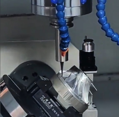
- Swarf Milling for Blade Surfaces: Swarf milling aligns the tool’s side with the blade surface, reducing scallop height and improving surface finish. For a blade height of 50mm, a step-over of 0.2mm and a 6mm tapered ballnose cutter at a 5-degree tilt angle minimize cusp errors.
- Zig-Zag Toolpaths for Hub Surfaces: A zig-zag pattern starting from the impeller center ensures consistent climb cutting, reducing tool marks. A 0.1mm step-over at 10,000 RPM maintains surface smoothness.
- Multi-Path Milling for Uniform Depth: Dividing the finishing pass into multiple paths with a constant axial depth of cut (0.05mm) prevents overcutting and enhances contour fidelity.
- Collision Avoidance: Narrow channels require dynamic tool axis adjustments to prevent interference with adjacent blades. CAM software calculates safe tool orientations using NURBS interpolation, ensuring a minimum clearance of 0.5mm.
Toolpath optimization reduces machining time by 15-20% while maintaining accuracy. For example, a 160mm diameter impeller with six blades can be finished in 2 hours using these strategies, compared to 2.5 hours with conventional three-axis methods.
Machine Calibration and Stability
Five-axis CNC machines must be calibrated to minimize volumetric errors. Systematic errors in linear and rotary axes can accumulate, causing deviations exceeding 0.006mm. Calibration involves:
- Laser Interferometry: Measures linear axis positioning errors to within 1 micrometer. Adjustments are made to compensate for backlash and thermal expansion.
- Rotary Axis Alignment: Ensures A and C axes are perpendicular to within 0.001 degrees using precision test bars and dial indicators.
- Thermal Compensation: Real-time monitoring of spindle and ambient temperatures adjusts tool positions. A 10°C temperature rise can cause a 12-micrometer error, which is reduced to 3 micrometers with compensation.
Machine stability is enhanced by minimizing vibrations. A spindle speed of 12,000 RPM and a feed rate of 1,200 mm/min for a 6mm cutter reduce dynamic errors. Regular maintenance, including lubrication and bearing checks, ensures consistent performance.
Tool Selection and Parameters
Tool selection directly impacts contour accuracy. Tapered ballnose end mills are preferred for their rigidity and ability to access narrow channels. Specific parameters include:
| Tool Type | Diameter (mm) | Taper Angle (°) | Flute Length (mm) | Coating | Application |
|---|---|---|---|---|---|
| Tapered Ballnose | 6 | 3 | 30 | TiAlN | Blade Finishing |
| Bullnose | 10 | 0 | 40 | AlCrN | Hub Roughing |
Tool parameters are optimized as follows:
- Spindle Speed: 10,000-15,000 RPM for finishing, balancing cutting efficiency and tool wear.
- Feed Rate: 800-1,500 mm/min, adjusted based on blade thickness to prevent deflection.
- Depth of Cut: 0.02-0.05mm for finishing passes, ensuring minimal material removal per pass.
Tool wear monitoring using acoustic emission sensors prevents surface degradation. Replacing tools after 4 hours of continuous machining maintains consistent accuracy.
Error Compensation Techniques
Contour errors arise from tool deflection, machine dynamics, and nonlinear interpolation. Compensation techniques include:
- Cutter Contact Point (CC) Compensation: Adjusts tool positions based on CC point data, reducing nonlinear errors from 19 micrometers to 1.5 micrometers. This involves recalculating tool center points using kinematic models.
- Force-Induced Deflection Compensation: Finite element analysis predicts blade deflection under cutting forces (e.g., 200N radial force). Toolpaths are adjusted to offset deflections up to 10 micrometers.
- Look-Ahead Control: Anticipates tool axis swings, reducing contour errors by 30% in high-speed machining (e.g., 2,000 mm/min).
Post-machining inspection using CMM verifies contour accuracy. A 160mm impeller machined with these techniques showed a maximum deviation of 5.8 micrometers, meeting the 0.006mm target.
Material Considerations
Impeller materials, such as Inconel 625 or stainless steel, affect machining parameters. High-strength alloys require lower feed rates (600-1,000 mm/min) and higher spindle speeds (12,000-18,000 RPM) to minimize work hardening. Cooling strategies, such as high-pressure coolant at 70 bar, reduce thermal distortion and improve chip evacuation, contributing to surface accuracy.
For example, machining a stainless steel impeller with a 6mm tapered ballnose cutter at 1,000 mm/min feed rate and 0.03mm depth of cut achieved a surface roughness of Ra 0.22 micrometers, supporting contour accuracy.
Process Validation and Quality Control
Validating the machining process involves iterative testing and measurement. A typical workflow includes:
- Trial Machining: Machine a prototype impeller to identify toolpath or parameter issues.
- CMM Inspection: Measure 100 points across blade surfaces to calculate contour deviations.
- Parameter Adjustment: Refine feed rates or tool angles based on inspection data.
Quality control ensures repeatability. Statistical process control (SPC) monitors key metrics, such as surface roughness (Ra < 0.3 micrometers) and contour deviation (< 0.006mm). A batch of 10 impellers machined with optimized parameters showed a 98% pass rate for contour accuracy.
Practical Implementation
Implementing these strategies requires integration of CAD/CAM software, machine tools, and metrology systems. Software like Siemens NX or CAMWorks generates toolpaths with NURBS interpolation, ensuring smooth transitions. A five-axis machining center, such as the Mikron UCP 710, provides the necessary rigidity and accuracy. Key steps include:
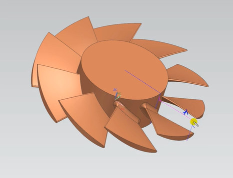
- CAD Model Preparation: Define blade surfaces with 0.001mm tolerance in the CAD model.
- CAM Programming: Simulate toolpaths to verify collision-free operation.
- Machine Setup: Use fixtures with 0.002mm clamping accuracy to secure the workpiece.
A case study of a 200mm diameter Inconel impeller machined on a five-axis CNC center achieved a contour accuracy of 0.0058mm after two iterations, demonstrating the effectiveness of this approach.
Conclusion
Achieving a contour accuracy of 0.006mm in impeller machining requires meticulous toolpath planning, machine calibration, tool selection, error compensation, and quality control. By leveraging five-axis machining capabilities and precise parameters, manufacturers can produce impellers with exceptional geometric accuracy, ensuring optimal performance in demanding applications. This systematic approach, grounded in technical expertise, provides a reliable framework for high-precision machining.