CNC (Computer Numerical Control) machining is a cornerstone of modern manufacturing, enabling the production of complex parts with high precision and efficiency. CNC factories leverage advanced machinery, sophisticated software, and systematic processes to meet the demanding requirements of industries such as aerospace, automotive, medical, and electronics. This article provides a detailed examination of how CNC factories achieve these outcomes, focusing on technical capabilities, process optimization, and quality assurance. The content is structured to offer clarity and depth, emphasizing experience and technical expertise without speculative trends or innovations.
Understanding Complex Parts in CNC Machining
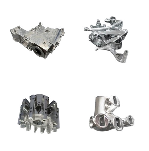
Complex parts are components with intricate geometries, tight tolerances, or specific material requirements that cannot be easily produced using manual machining methods. These parts often feature non-linear curves, undercuts, deep cavities, or organic shapes, requiring advanced machining techniques. Industries like aerospace demand parts such as titanium turbine blades with tolerances as tight as ±0.005 inches (±0.127 mm), while medical applications require components like orthopedic implants with smooth surface finishes (Ra 0.4 µm or better). CNC factories address these needs through a combination of advanced equipment, precise programming, and skilled operations.
The complexity of a part is determined by factors such as:
- Geometric intricacy: Features like undercuts, thin walls, or compound angles.
- Tolerance requirements: Specifications often range from ±0.01 mm to ±0.05 mm for high-precision parts.
- Material properties: Hard materials like titanium or Inconel versus softer materials like aluminum or plastics.
- Surface finish: Requirements for smoothness, often measured in Ra (Roughness Average) values.
CNC factories are equipped to handle these demands through specialized machinery and processes, as detailed below.

Advanced CNC Machinery for Complex Geometries
CNC factories rely on a variety of machine types to produce complex parts, each designed for specific tasks. The most common machines include CNC mills, lathes, routers, and multi-axis systems, with capabilities tailored to intricate designs.
Multi-Axis CNC Machines: Multi-axis machines, particularly 5-axis CNC mills, are critical for machining complex parts. Unlike 3-axis machines, which operate along X, Y, and Z axes, 5-axis machines add two rotational axes (A and B or C), allowing the cutting tool to approach the workpiece from multiple angles. This enables the production of organic shapes, undercuts, and complex contours without repositioning the workpiece, reducing setup time and improving accuracy. For example, a 5-axis CNC mill can machine a part with dimensions up to 2000 x 800 x 1000 mm, with positional accuracy of ±0.005 mm.
CNC Lathes: CNC lathes are used for cylindrical parts, such as shafts or bushings, with high precision. Advanced lathes, like Swiss-style machines, can handle non-cylindrical shapes and perform simultaneous milling and turning operations. A typical CNC lathe operates with two axes (X and Z) but can include additional axes for complex operations, achieving tolerances as low as ±0.002 mm.
Specialized Machines: For specific applications, CNC factories employ machines like wire EDM (Electrical Discharge Machining) or water jet cutters. Wire EDM is ideal for hard materials like titanium, offering precision cuts with tolerances of ±0.001 mm. Water jet cutters, using high-pressure water mixed with abrasives, are suited for heat-sensitive materials, maintaining material integrity with no thermal distortion.
The table below summarizes key CNC machine types and their capabilities for complex parts:
| Machine Type | Axes | Typical Applications | Tolerance Range | Max Part Size |
|---|---|---|---|---|
| 3-Axis CNC Mill | X, Y, Z | Flat surfaces, simple geometries | ±0.01 mm to ±0.05 mm | Up to 1000 x 800 x 600 mm |
| 5-Axis CNC Mill | X, Y, Z, A, B/C | Complex contours, organic shapes | ±0.005 mm to ±0.02 mm | Up to 2000 x 800 x 1000 mm |
| CNC Lathe | X, Z (up to 5 axes) | Cylindrical parts, intricate designs | ±0.002 mm to ±0.01 mm | Ø 500 mm x 1000 mm |
| Wire EDM | 2-4 axes | Hard materials, precision cuts | ±0.001 mm | Up to 600 x 400 x 300 mm |
Precision Programming with CAD/CAM Software
The foundation of CNC machining lies in precise programming using CAD (Computer-Aided Design) and CAM (Computer-Aided Manufacturing) software. CAD software, such as SolidWorks or AutoCAD, allows engineers to create detailed 3D models of complex parts, defining geometries, dimensions, and tolerances. These models are then translated into machine-readable G-code and M-code via CAM software, such as MasterCAM, which specifies tool paths, spindle speeds (e.g., 10,000–20,000 RPM for high-speed milling), and feed rates (e.g., 100–500 mm/min for aluminum).
Tool Path Optimization: CAM software optimizes tool paths to minimize machining time and tool wear while ensuring precision. For complex parts, tool paths must account for undercuts, deep cavities, or thin walls, often requiring custom tools like T-shaped or lollipop cutters. For example, undercuts with a width of whole millimeter increments (e.g., 2 mm, 3 mm) are preferred to avoid custom tooling costs.
Simulation and Verification: Modern CNC factories use simulation software to model the entire machining process, including tool movements, spindle interactions, and workpiece fixturing. This reduces the risk of collisions, which can damage tools or parts, and ensures that the programmed paths align with the CAD model. A typical simulation can predict machining accuracy within ±0.01 mm, enhancing reliability.
Pain Point: Programming Complexity: One challenge in CNC machining is the time required to program complex parts. For instance, a 5-axis machining program for an aerospace component with multiple curved surfaces may take several hours to develop and verify, especially if non-standard tools or custom fixtures are needed. Skilled programmers mitigate this by using standardized templates and libraries, reducing programming time by up to 30%.

Material Versatility and Machining Parameters
CNC factories handle a wide range of materials to meet diverse industry needs, from metals like aluminum (6061, 7075) and titanium (Ti-6Al-4V) to plastics like ABS or PEEK, and even composites or ceramics. Each material requires specific machining parameters to achieve desired outcomes without compromising quality.
Material-Specific Parameters: For example, machining titanium requires lower cutting speeds (50–100 m/min) and higher feed rates (0.05–0.15 mm/rev) compared to aluminum (200–600 m/min, 0.1–0.3 mm/rev) to manage heat buildup and tool wear. Coolant selection, such as water-based emulsions for aluminum or oil-based for titanium, also plays a critical role in maintaining surface quality (e.g., Ra 0.8 µm for medical implants).
Fixture Design: Proper fixturing ensures that workpieces remain stable during machining, especially for complex parts with thin walls or irregular shapes. CNC factories use pneumatic vises or custom jigs to secure parts, minimizing vibration and ensuring positional accuracy within ±0.005 mm.
The following table outlines typical machining parameters for common materials:
| Material | Cutting Speed (m/min) | Feed Rate (mm/rev) | Coolant Type | Surface Finish (Ra, µm) |
|---|---|---|---|---|
| Aluminum 6061 | 200–600 | 0.1–0.3 | Water-based | 0.8–1.6 |
| Titanium Ti-6Al-4V | 50–100 | 0.05–0.15 | Oil-based | 0.4–0.8 |
| Stainless Steel 316 | 80–150 | 0.08–0.2 | Oil-based | 0.8–1.2 |
| PEEK | 100–200 | 0.1–0.25 | Dry or air | 0.4–1.0 |
Quality Control and Inspection
Ensuring that complex parts meet specifications is critical in CNC machining. Factories implement rigorous quality control (QC) processes, including in-process monitoring and post-machining inspection, to verify dimensional accuracy and surface quality.
In-Process Monitoring: Closed-loop CNC systems use encoders to monitor axis positions in real time, correcting deviations within ±0.002 mm. Sensors also track spindle speed and tool wear, adjusting parameters to maintain consistency.
Coordinate Measuring Machines (CMM): Post-machining, CMMs measure part dimensions against CAD models, ensuring tolerances are met. For example, a CMM can verify a part’s geometry to within ±0.001 mm, critical for aerospace components like landing gear.
Surface Finish Inspection: Profilometers measure surface roughness, ensuring finishes meet requirements (e.g., Ra 0.4 µm for medical devices). Visual inspections and non-destructive testing (NDT) methods, such as ultrasonic testing, detect internal defects.
Pain Point: Tolerance Verification: Verifying ultra-tight tolerances for complex parts can be time-consuming, especially for large batches. Automated CMMs and laser scanning reduce inspection time by up to 50%, but manual checks may still be required for critical features, adding to production time.
Systematic Workflow for Efficiency
CNC factories employ a systematic workflow to streamline the production of complex parts, from design to delivery. The process includes:
- Design Phase: Engineers create CAD models, specifying tolerances and material requirements.
- Programming: CAM software generates G-code, optimized for the chosen machine and material.
- Setup: Operators configure machines, install tools, and secure workpieces using fixtures.
- Machining: The CNC machine executes the program, with real-time monitoring to ensure accuracy.
- Inspection: Parts undergo CMM and surface finish checks to verify compliance.
- Finishing: Additional processes like polishing or coating are applied if required.
This structured approach minimizes errors, reduces lead times, and ensures consistent quality, making CNC factories reliable partners for complex part production.
Conclusion
CNC factories meet the machining needs of complex parts through a combination of advanced machinery, precise programming, material versatility, and rigorous quality control. Multi-axis machines, such as 5-axis mills and CNC lathes, enable the production of intricate geometries with tolerances as tight as ±0.001 mm. CAD/CAM software ensures accurate tool paths, while systematic workflows and quality inspections guarantee reliability. By addressing challenges like programming complexity and tolerance verification, CNC factories deliver high-precision parts for industries with stringent requirements, establishing themselves as trusted partners in modern manufacturing.