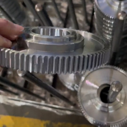
Large-diameter end gear discs, also referred to as multi-tooth discs or ratchet discs, are precision components critical for accurate indexing and positioning in applications such as CNC machine tools, machining centers, and high-precision indexing devices. With diameters typically exceeding 500 mm and tooth counts often reaching 360, these discs pose significant machining difficulties due to their size, tight tolerances, and susceptibility to deformation. This article provides a detailed, systematic methodology for machining large-diameter end gear discs, emphasizing optimized process routes, refined gear tooth finishing techniques, and effective packaging and transportation practices to achieve high precision and minimize deformation.
Introduction to End Gear Discs
End gear discs serve as precision indexing elements, functioning similarly to clutches with identical tooth counts to provide automatic centering and high positioning accuracy. They are commonly used in CNC lathe turrets, milling machine rotary tables, and other indexing mechanisms. Available in straight-tooth and curved-tooth profiles, straight-tooth discs are preferred for their machining simplicity and superior positioning and repeat positioning accuracy. The primary difficulties in machining large-diameter end gear discs include managing residual stresses, controlling deformation, and achieving consistent tooth geometry across a high tooth count.
Machining Process Route
The machining process for large-diameter end gear discs is designed to minimize errors, reduce residual stresses, control deformation, and optimize efficiency. The process route is tailored for discs with diameters greater than 500 mm and tooth counts exceeding 144, typically made from 40Cr or 38CrMoAl, which undergo heat treatments such as quenching, tempering, and nitriding. The following table outlines the process sequence:
| Step | Description |
|---|---|
| Forging | Shapes raw material into a disc blank. |
| Annealing | Reduces internal stresses to enhance machinability. |
| Rough Turning | Establishes preliminary dimensions. |
| Quenching and Tempering | Improves material strength and toughness. |
| Semi-Finish Turning | Refines dimensions for subsequent operations. |
| Surface Grinding | Ensures flatness of reference surfaces. |
| Gear Milling | Forms initial tooth profiles. |
| Chamfering | Deburrs edges for safety and fit. |
| Low-Temperature Aging | Relieves residual stresses to reduce deformation. |
| Outer and Inner Diameter Grinding | Achieves final external and internal dimensions. |
| Rough and Semi-Finish Gear Grinding | Refines tooth profiles progressively. |
| Nitriding | Hardens surfaces for wear resistance. |
| Final Surface and Diameter Grinding | Meets dimensional and surface finish specifications. |
| Reference Surface Lapping | Polishes critical surfaces for flatness. |
| Finish Gear Grinding | Achieves precise tooth geometry and surface finish. |
This sequence incorporates multiple heat treatments and precision machining steps to maintain structural integrity and dimensional accuracy, addressing deformation risks from residual stresses.
Difficulties in Gear Tooth Finishing
Finish grinding of gear teeth is the most technically demanding stage due to the large diameter and high tooth count. Specific difficulties include:
- Deformation: Residual stresses from heat treatment and machining forces cause warping, affecting dimensional accuracy.
- Alignment Challenges: The large workpiece size complicates precise fixture and machine setup.
- Grinding Wheel Wear: Large contact areas accelerate wheel wear, leading to indexing errors.
- System Errors: Machine inaccuracies, environmental variations, or improper fixturing can compromise precision.
To mitigate these issues, grinding must occur in a controlled environment (20°C ± 5°C) free from vibrations or thermal fluctuations. The indexing device must exceed the workpiece’s precision grade, and paired discs should be machined on the same equipment with consistent tooth angles, marked for pairing to ensure optimal meshing.
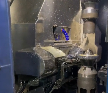
Gear Tooth Finishing Techniques
Precision gear tooth finishing requires meticulous control over equipment, tools, and processes. The following techniques ensure high accuracy and minimal deformation.
Machine Tool Setup
Prior to grinding, the machine tool is inspected for system errors. Lubrication systems, oil holes, and guideways are checked to prevent crawling. Feed and reversal speeds are verified for consistency, and the machine is run idle for at least two hours to stabilize performance. These preparations ensure reliable operation and reduce machining errors.
Grinding Wheel Selection
Grinding wheel choice is critical for quality and efficiency. Wheels should exhibit low wear, high durability, and excellent cutting performance. White corundum wheels with medium softness and self-sharpening properties are preferred. Grain sizes are selected based on the grinding stage:
- Rough grinding: 46#
- Semi-finish grinding: 60#
- Finish grinding: 100# or 120#
Frequent wheel dressing maintains sharpness, preventing deflection and ensuring uniform tooth profiles. Proper maintenance reduces indexing errors and improves surface finish.
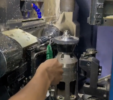
Fixture Alignment
Due to the large workpiece size, fixture alignment is challenging but essential. Contact surfaces are cleaned and, if needed, lapped with an oilstone to ensure flatness. Alignment accuracy is controlled within one-third of the workpiece’s tolerance to minimize setup errors, reducing the need for repeated adjustments.
Workpiece Clamping
Before clamping, reference surfaces are inspected for burrs, damage, or irregularities. The contact area between the workpiece and fixture must exceed 90% to ensure stability. Proper clamping prevents movement during grinding, maintaining dimensional accuracy.
Grinding Allowance Control
Grinding allowance is carefully managed to preserve the nitrided surface layer and ensure indexing accuracy. A pre-finish grinding allowance of 0.05–0.10 mm is typical, with slightly less for nitrided surfaces to protect the hardened layer (700–900 HV). Tooth measurements follow milling protocols, with adjustments to meet paired disc thickness requirements.
Grinding Process Parameters
The equal-cycle forming method is used, involving continuous indexing and incremental depth cuts to minimize deformation. Excessive feed rates are avoided to prevent heat buildup and wheel wear, which cause uneven material removal. Recommended parameters are:
| Grinding Stage | Feed Rate (mm/min) | Depth of Cut (mm) |
|---|---|---|
| Rough Grinding | 50–80 | 0.02–0.05 |
| Semi-Finish Grinding | 30–50 | 0.01–0.03 |
| Finish Grinding | 20–30 | 0.005–0.01 |
These parameters, combined with skilled operation, achieve tooth profile tolerances within ±0.005 mm and surface roughness of Ra 0.2–0.4 µm.
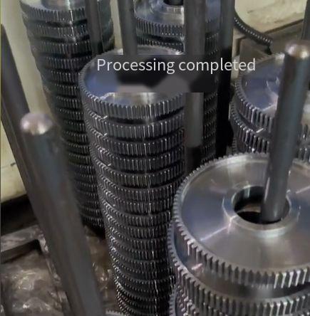
Storage and Packaging Procedures
Post-machining handling is critical to prevent deformation that could compromise indexing accuracy. The following procedures ensure the gear discs remain protected during storage and transportation.
Inspection and Cleaning
After finish grinding, a qualified inspector verifies dimensions and surface quality using precision tools like coordinate measuring machines (CMM) and profilometers. Paired discs are marked for meshing accuracy. Surfaces are cleaned with cotton yarn and 180-grade solvent gasoline to remove contaminants. Rust is inspected under adequate lighting, and any corrosion is treated before anti-corrosion application.
Anti-Corrosion Application
Anti-rust oil or grease is applied using a brush-coating method, ensuring a uniform, bubble-free coating on gear teeth and reference surfaces. This protects against corrosion during storage and transportation, preserving surface integrity.
Packaging Method
Coated discs are placed flat on dedicated racks. Sodium benzoate anti-rust paper is applied with the waxed side outward. Paired discs are meshed together, wrapped tightly with anti-rust paper from inner to outer diameters, and secured in a crate to prevent movement. Flat placement avoids stress concentrations that could cause deformation.
Storage Environment
Discs are stored in a controlled environment (20°C ± 5°C) free from moisture, vibrations, or thermal fluctuations. Dedicated racks support the discs evenly to prevent warping, ensuring long-term precision retention.
Quality Assurance
Quality control is integral to the process, ensuring compliance with design specifications. Key measures include:
- Dimensional Checks: Tooth profiles, pitch accuracy, and surface flatness are measured with CMM, maintaining tolerances within ±0.005 mm.
- Surface Finish: Profilometers verify surface roughness (Ra 0.2–0.4 µm).
- Hardness Testing: Vickers or Rockwell testers confirm nitrided surface hardness (700–900 HV).
- Pairing Accuracy: Meshing tests ensure indexing errors are within 0.01°.
These checks guarantee reliable performance in high-precision applications.
Conclusion
Machining large-diameter end gear discs demands a disciplined approach to address their size and precision challenges. Through an optimized process route, precise gear tooth finishing, and robust storage and packaging, manufacturers can achieve exceptional indexing accuracy and minimize deformation. This methodology, grounded in extensive experience, ensures reliable production of high-precision components for CNC machine tools and indexing devices, enhancing their performance and durability in demanding industrial applications.